Designation of sockets and switches on construction drawings and electrical diagrams.
Any construction process or installation of electrical circuits of buildings and structures begins with the project. For ease of orientation in numerous types of mounted equipment, as well as to eliminate mounting errors, there are conventions. It is not necessary to remember them all. It is enough to know the regulatory documents that you can look into when a difficult situation arises. Consider how to find out where the sockets and switches are in the drawing.
Regulatory documents
The main construction or installation document is the project. SNiPs and GOSTs - more global documents that disseminate their regulations throughout the state or industry. A project is a narrower document in this regard. He extends his regulation to a specific object.
The project should be universal in terms of understanding the conventions of all categories of specialists involved in installation. For this purpose, state and industry regulatory documents have been developed that regulate the type of symbols for all categories of mounted equipment and its elements (SNiPs and GOSTs).
Electrical equipment also has a legend.
There are two main varieties of electrical designations:
- The symbol of electrical equipment (in particular, sockets and switches) in the construction drawings.
- Symbol of electrical equipment on electrical diagrams.
Such designations have a significant difference. Therefore, they should be considered separately. But first, you need to understand the regulatory documents that establish the rules in accordance with the graphic designations of one or another electrical equipment.
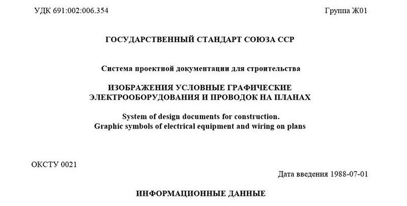
Currently, the following standard is valid in the territory:
GOST 21.614–88 “Conventional graphic images of electrical equipment and wiring on the plans” from the section “System of design documentation for construction”.
This state standard was introduced back in 1988.
Symbols for electrical equipment
Only this document regulates the graphic designations of electrical equipment on plans, diagrams and drawings. In particular, images of household and industrial switches, sockets.
Other electrical equipment (their graphic symbols) are standardized by another document:
GOST 2.721–74 “Conventional graphic designations in diagrams”.
The electrical circuits of power and operational circuits of electrical equipment are made using the graphic symbols specified in this GOST.
Electrical Conventions
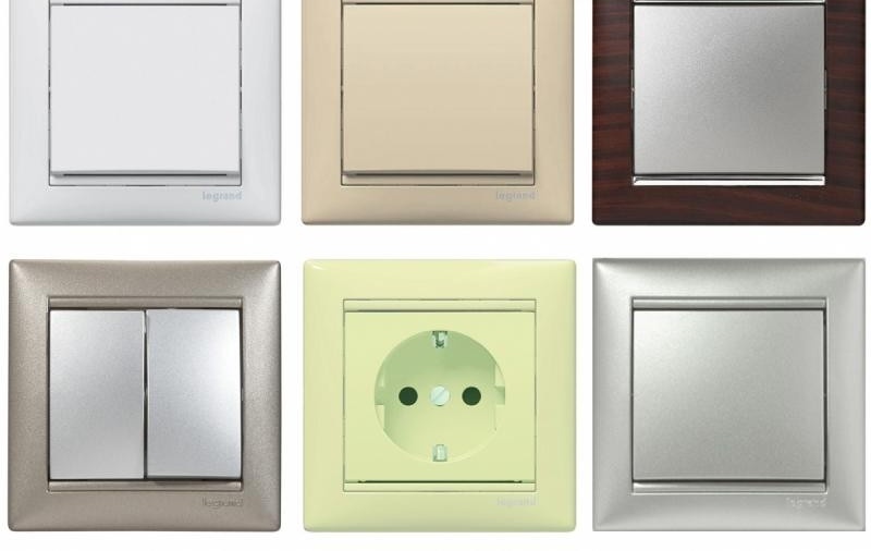
Designation of sockets
There are sockets of various types and purposes. Their performance depends on the voltage class, degree of protection, the presence of grounding contacts, installation method, etc.Let's consider step-by-step graphic conventions for each type of outlet.
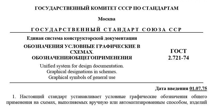
On building plans, diagrams, drawings, a conventional graphic designation of sockets for hidden wiring is performed as follows:
General conditional graphic representation of outlets
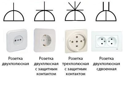
Graphic symbol for open wiring outlets is as follows:
General conditional graphic representation of outlets
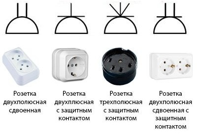
Conventional graphic designations of sockets of waterproof design on the diagrams and construction drawings are performed as follows:
General conditional graphic representation of outlets
In the IP encoding depicted on electrical equipment, an indicator of the degree of protection of the equipment casing from mechanical damage to live parts and moisture on them is encrypted. IP - capital letters of the expression Ingress Protection Rating (eng. - degree of protection against penetration). The classification of electrical equipment, according to this indicator, meets the international standards IEC 60529, DIN 40050, as well as GOST-14254.
The encoding of the degree of protection is compiled as follows:
IP X1X2 AM where:
X1 - a figure characterizing the degree of protection of live parts of the equipment from the ingress of solid particles;
X2 — a figure characterizing the degree of protection of live parts of the equipment from moisture;
AM - letters characterizing the degree of protection of equipment from the penetration of people to live parts. The first letter can be A, I, C, D. Each of them has its own characteristics. The second letter carries additional information, for example, about the class of operating voltage, about equipment tests and more. This letter can be H, M, S, W.
For ease of orientation in the encoding of the degree of protection, a look-up table is provided.
Electrical characteristics according to IP coding.
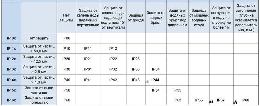
Reference table
Graphic designations of switches
Switches, like sockets, are classified according to their design. Which, in turn, depends on the class of the operating voltage of the circuit breaker, the installation method, degree of protection and more.
The main types of circuit breakers and their graphic symbols on the building plans, drawings and diagrams are given below.
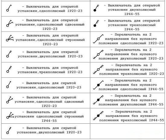
Designation of the main types of switches
Illustrative example:
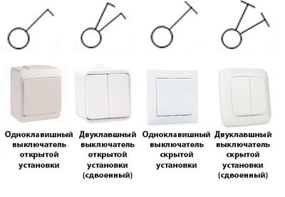
Circuit Breaker Symbols
The international IP classification applies to switches similar to sockets.
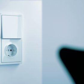
Combined electrical equipment deserves special attention. For the equipment in question, this is a combined unit from a socket and a switch. It also has its own graphic designation.
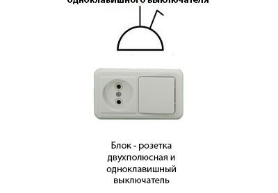
Combined electrical equipment
Symbols on electrical diagrams
With electrical circuits easier. The classification of switches and sockets by their design in this case is not particularly taken into account. The electrical equipment in question has such graphic symbols.
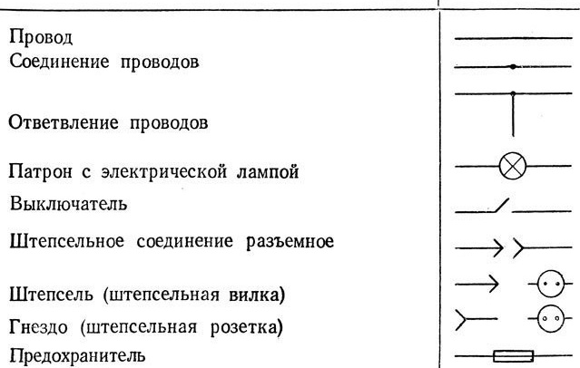
Electrical designations
To designate protective circuit breakers on electrical circuits, such conventions are adopted.
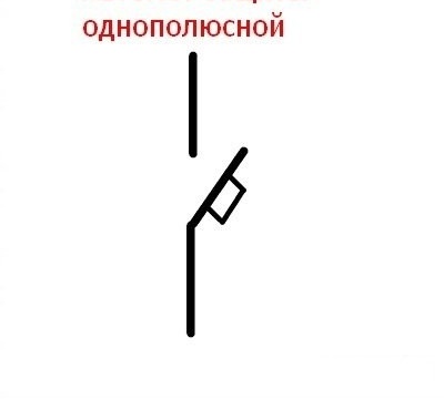
Conditional graphic designation
Three-pole and four-pole circuit breakers have this designation.
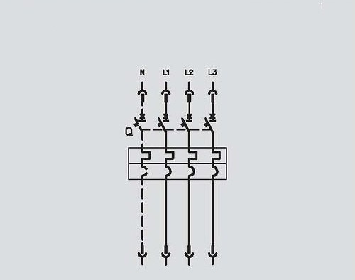
Symbol
And also, as an example, below is the electrical diagram of the power supply of a room or building. The circuit designates an input three-pole 380 V circuit breaker, from which the phase wires go to a group of twelve single-pole circuit breakers. These switches form a branched and protected electrical circuit 220 V.
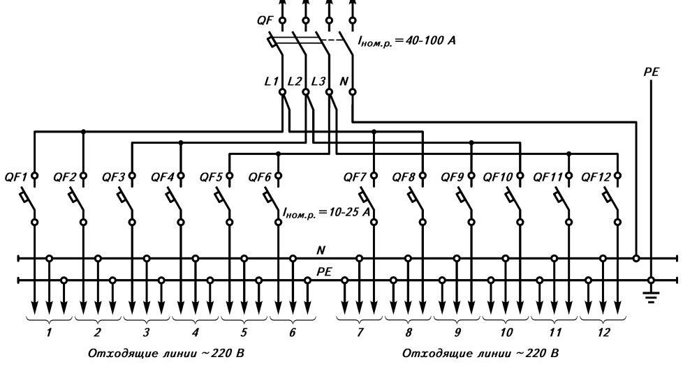
Symbols of circuit breakers (automatic) on the electric circuit
Modern electrical equipment is updated with new developments at an impressive speed. Given this, a situation arises in which the development of new conventions and the approval of modern state standards is a lagging process.Therefore, it is not scary if there is no graphic symbol for specific electrical equipment. For its designation, the most approximate in meaning is chosen. And in the designation section of the project, clarification is made on this subject.