Do-it-yourself wiring in a wooden house - requirements, project preparation and step-by-step installation instructions

The technology for wiring devices in wooden houses has its own characteristics. Not only will you need to pull the cable from the nearest substation to connect to the network, and wiring indoors must be carried out in compliance with special safety standards.
Content
Wiring requirements
Wood is the most popular material used in the construction of private housing. Despite its advantages, wood is a flammable and highly flammable material.
Regardless of the material - brick, gas silicate blocks, concrete, timber, in the event of a fire, an open fire is thrown onto furniture and the interior of the room. First, everything burns down indoors, and after that the load-bearing walls, partitions and roof begin to burn.
Basic requirements for wiring in buildings made of wood:
- Safety - wiring should be laid in such a way as to minimize the likelihood of overheating and ignition of the cable, as well as to prevent the transfer of open flame to adjacent wooden structures.
- Design - the technical characteristics and operational qualities of the wires and components used should correspond to the calculated peak load on a specific section of the power grid. To prevent heating, the cable section is selected with a margin of 20-30%.
- Laying method - electrification of wooden buildings is preferable to perform in an open way. This allows you to seamlessly and at regular intervals to diagnose the status of the power grid.
- Insulation - the location of the input unit (electrical panel) must be isolated from the interface with wooden structures. Ideally, if the electrical panel is installed in a room with a partition made of non-combustible materials.
- Conductor - as a conductor it is better to use a three-core copper cable with insulation from non-combustible materials. It is strictly forbidden to lay the cable in PVC corrugation.
- Automation - a circuit breaker must be installed for each group in the power grid.The rated current of the circuit breaker is selected in accordance with the load on the site. It is extremely not recommended to overstate the current rating, as this will lead to overheating of the conductor.
It is not recommended to carry out independent laying of the power cable and installation of the electric network without appropriate experience - this should be done by specialists. But every owner of a private house is required to know the basic rules of electrification. This will allow him to diagnose the existing wiring, as well as provide an opportunity to monitor the quality of the work of hired electricians.
Regulations

Electrical installation rules is the main document for the design of electrical wiring
General requirements and rules for electrical wiring are described in the following documents:
- PUE, edition 7 - the main document used in the design of the power grid. It describes in detail the choice of conductor, switchgear, automation and lighting.
- SNiP 3.05–06–85 - wiring device in old and new houses. Wiring methods and rules for entering a power cable into a living room.
- SNiP 31–02 - requirements for the installation of the power supply system in residential buildings. The document complies with the rules and regulations described in the EMP.
The information contained in these sources is described in technical language and may not be understood by an unqualified specialist. For self-study, we recommend that you rely on the "Electrical Installation Rules", as this document most clearly formulates the meanings and concepts necessary for wiring in private homes.
Preparation of a power supply project
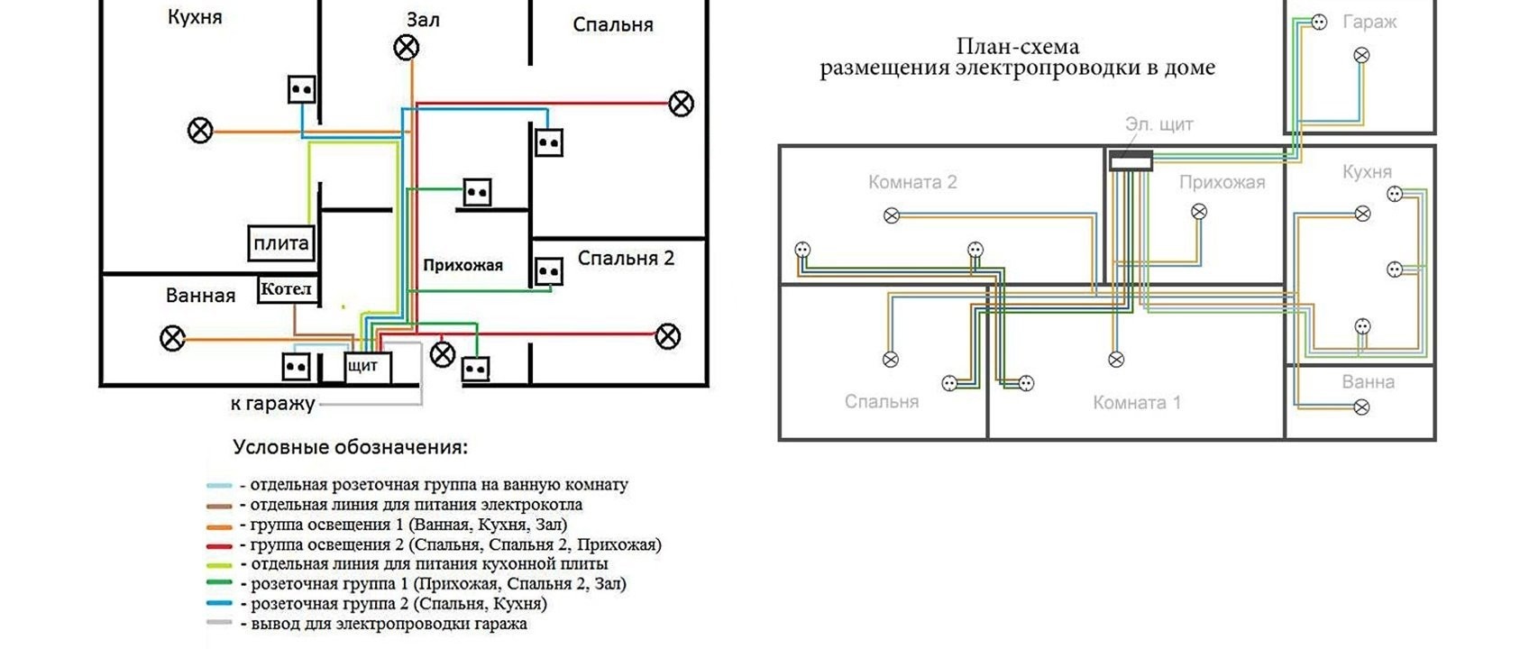
An example of two circuits of the electrical network in a wooden house
The electrification of a residential building begins with the development of an individual project. For this, it is necessary to fill out an application at the branch of OJSC Regional Electric Networks at the place of residence.
After consideration of the application by the governing body, an agreement will be prepared and the technical conditions necessary for connection to the local electric network. Then you can begin to design the power supply, which is carried out in the following sequence:
- Total power - based on the available household appliances, the total power consumption is calculated with a margin of 30%.
- Project - taking into account the plan of a residential building, a diagram is drawn with an image of the input cable, electrical panel, wiring, socket groups, lighting, etc.
- Cable section - for each group in the mains, the type and section of the conductor is selected.
Electricity scheme of a residential building according to the European standard
- Junction boxes - for apartment buildings, the ideal location of junction boxes for outlet groups and lighting fixtures is selected.
- Cable routing - the project indicates the optimal path for laying the conductor. Additionally, at each site, the distance from the main building elements is indicated: floor, ceiling, doorway, windows.

When drafting a project, the PUE should be guided. According to this document, electrical wiring is laid strictly in the vertical or horizontal direction. Optimum rotation angle - 90o.
The outlet group, switches and junction boxes must be located in open areas with free access. Usually, switches are mounted 80–150 cm from the floor, and a socket or socket group is 50–80 cm. The number of sockets varies 1–6. The exact amount depends on the size of the room, but at least one piece per 6m2.
When designing a cable route, it should be borne in mind that the minimum distance from the openings should not be less than 10 cm. If the cable may touch the metal elements along the route, it will be retracted by 15-30 cm in any convenient direction.
Wire and device selection
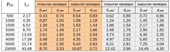
Wire cross section taking into account the total power of the power supply
When arranging private power grids, two types of cables are used: NYM and VVGng. A NYM type cable is a power cable that complies with European standards and is used for laying electrical networks with a nominal voltage not exceeding 660 V. VVGng cable is a bare power cable, in a double vinyl braid, operating in networks with a constant voltage of not more than 1 kW.
The cross-section of the cable for laying electrical networks is determined in "mm2". For designation, marking is applied to the cable insulation and is indicated by two numbers. The first digit indicates the number of wires inside a single insulation. The second digit is the cross-sectional area of the conductor. For example, when an electrician says that a three-core copper cable is needed one and a half squares, this means NYM cable 3x1.5 mm.
The easiest way to determine the minimum cross-section of the core of a power cable for a particular section of the network is a special table. This method is proven, as it is used in the design of electrical networks in apartment buildings. You can get acquainted with the table for selecting the cross section of the core in the photo above.
As a rule, for outlet groups, a copper cable with a cross section of 2.5–4 mm is used, and for lighting - an aluminum cable with a cross section of 1.5–2.5 mm. In the case of wooden houses, it is recommended to use only copper wiring, as this will protect the power grid from overheating.
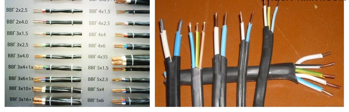
Wire of various sections for the installation of electrical wiring in a wooden house
According to the PUE, each section of the power supply network is equipped with a residual current device and a circuit breaker designed for the corresponding current indicators. To calculate the current strength, the standard formula –I = P / U · cosφ is used, where:
- I is the current strength;
- P is the total power of electrical appliances connected to one section of the power grid;
- U is the voltage in the mains;
- cosφ is a constant coefficient. In household networks, it is almost always equal to 1.
For example, it is required to determine the current strength for a network section to which household equipment with a total capacity of 3 kW will be connected. I = 3000/220 = 13.64 A. Taking into account a small margin and rounding, it turns out that for this section an RCD and a diphomatate are required for a rated current of 16A.
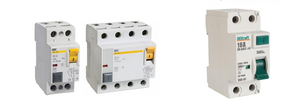
RCD and circuit breaker for wiring
To determine the type of circuit breaker, it is necessary to calculate the minimum current strength during a short circuit: IKZ = 3260 x S / L, where S is the cross-section of the conductor in mm2, L is the length of the conductor in m. Typically, in networks with a mixed load, which will be presented in most private houses, type C machines are used.
Sockets are selected taking into account the power of electrical appliances. Usually, these are sockets with grounding, rated at 16 A current. It is worth remembering that if it is planned to use several electrical appliances in a particular room, it is better to install a socket group for 2-3 products than to use a “tee” in the future.
Selection of input cable and automation
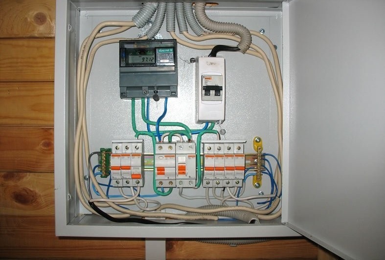
On the left is an electric meter, on the left is an RCD with a lead-in cable
Input cable selection and difavtomat carried out by analogy with the conductor for local sections of the power grid. For this, it is necessary to calculate the estimated load on the network by summing the maximum power of all connected electrical appliances. The power of the device is indicated in the specification or operating instructions.
The input difomatat is selected taking into account the phase of the network and rated currents so that at peak load the structure is not de-energized, but only an open circuit occurs in the electrical panel.
For electrical wiring in private wooden houses, a one- or two-pole machine is used, which is installed after the electric meter. In more detail, the calculation of the current strength for the selection of RCD and diphatomate was described in the previous section.
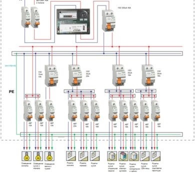
Type of single-phase power
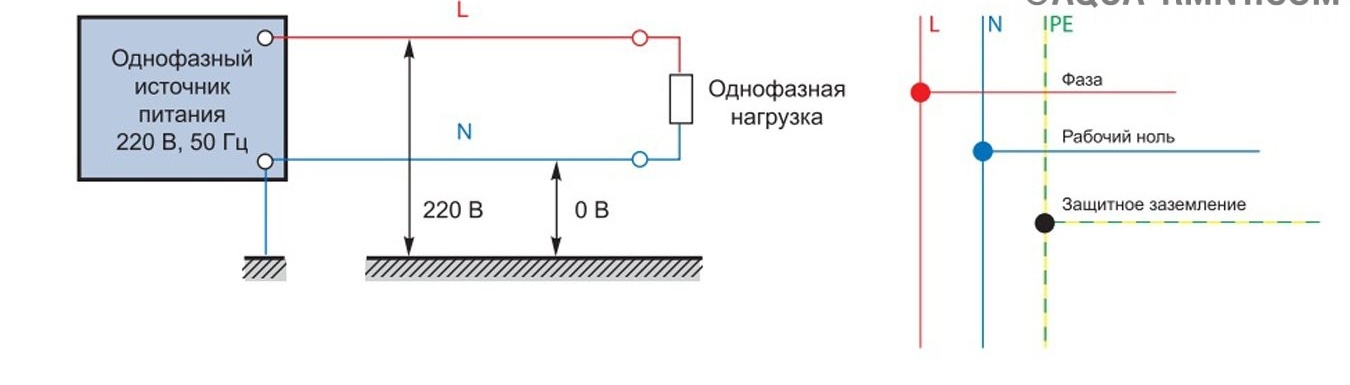
Single-phase power supply circuit diagram
A single-phase electrical network is the most common way to electrify private houses and typical apartments. The rated voltage in a single-phase network is 220 V with a frequency of 50 Hz.
To power the building, a two-core or three-core power cable is used, which is fed from the local substation to the electrical switchboard inside the building.
In the first case, a two-core cable without grounding is used. In the second case, a three-core cable is used with a working "phase" (L), reverse "zero" (N) and protective earth.
You might like the idea of arranging retro-style electrical wiring. In more detail about installation of the system in a wooden house in our next material:https://aquatech.tomathouse.com/en/ehlektrosnabzhenie/retro-provodka-v-derevyannom-dome.html.
DIY electrical wiring in a wooden house - step by step instructions
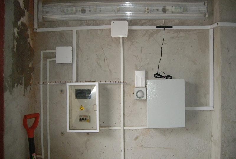
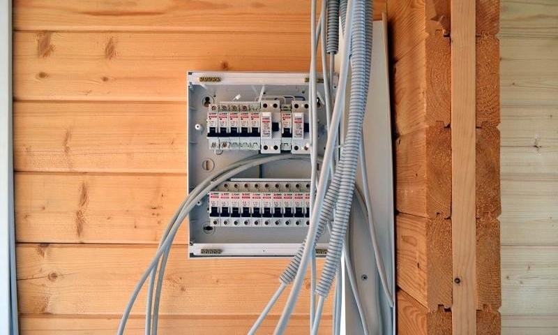
Optimally, if the switchboard is installed in a special room with a concrete partition or wall
The technology for installing electrical wiring in a wooden house will consist of several stages: supplying a power cable to the house, installing a switchboard, laying a cable route, installation of switches and sockets, connection of contacts and health check.
For work, you will need to prepare an electric drill with a crown nozzle, a screwdriver, a cross and slotted screwdriver, an indicator screwdriver and protective rubber gloves.
Installation of distribution board
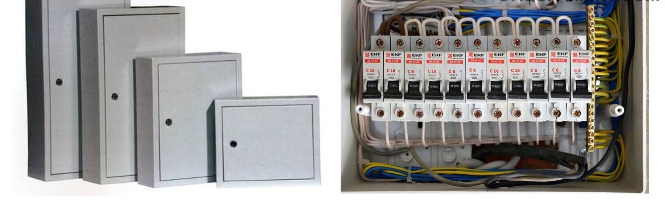
Distribution board for a private house for 12-24 modules
The switchboard is a device for inputting a power cable and distributing incoming electrical energy. Inside the switchboard there is electrical equipment responsible for the connection, metering, safety and correct operation of the power supply system.
Ready-made distribution boards from the manufacturer are a plastic, metal or combination box with a door, din rail, zero and ground bus. The dimensions of the shield are selected according to the number of modules used. For wooden houses, a shield for 12-15 modules is enough.
Installation of the shield consists of several stages:
- The switchboard is mounted in a vertical position 120-150 cm above the floor. Optimally, if the contacted surface is made of concrete, brick or a gas silicate block. In a wooden house, it is better to highlight a special utility room, where it is possible to equip a suitable surface.
- To install the shield, you will need to remove the front part with the door, which is fixed on plastic latches or small screws. Marking is applied to the surface of the wall, and holes for plastic plugs are drilled.
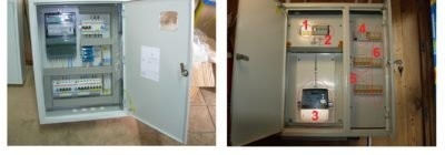
Example of switchboard layouts in residential buildings
- For fastening, the back of the flap leans against the wall and "bites" on the screws. After leveling, the screws are screwed to the stop. Then, at the entrance of each line to the DIN rail, an RCD, a counter, two-pole machines are installed. Modules are mounted in decreasing current strength.
- To connect the machines, jumpers are cut from the cable or comb bus. When using jumpers, the cable is stripped 1 cm. The comb is cut according to the number of installed machines.
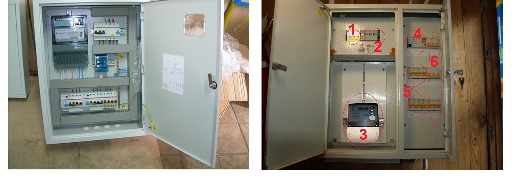
When using a shield for 16-24 modules, as a rule, there are two din-rails in it. It is better to install an input automatic machine, a counter and an RCD in the required amount on the upper guide.
On the lower dynke will be located circuit breakers. This type of module distribution will allow for faster and more convenient connection. After mounting all the elements, it is recommended that the modules be labeled taking into account their group. The assembly sequence of the shield is shown in the video below.
Video on the topic: assembly and layout of the switchboard
Cable entry into the room
Laying the power cable to the apartment building through the air
The input of the power cable into a residential building can be performed in two ways: underground and by air. The first method is more reliable, since an armored cable protected by a corrugated pipe will be used. In this case, the wiring itself will be located under a 30-40 cm layer of earth.
To lay the cable, a trench with a depth of 70–80 cm is pulled out. A layer of fine-grained sand is poured at the bottom of the trench 15–20 cm and well compacted. Further, a protective corrugation is laid on a sand cushion, through which an armored cable is passed. Then the corrugated pipe is filled up with 10-15 cm layer of sand. At the end, the pipe is completely walled up in the ground.
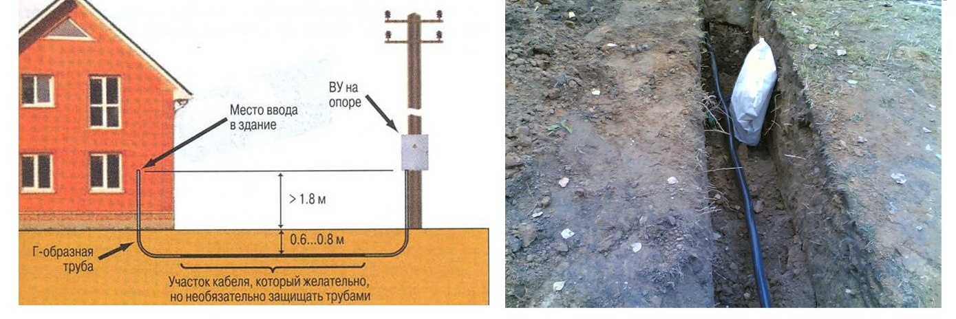
Laying a power cable to a residential building underground
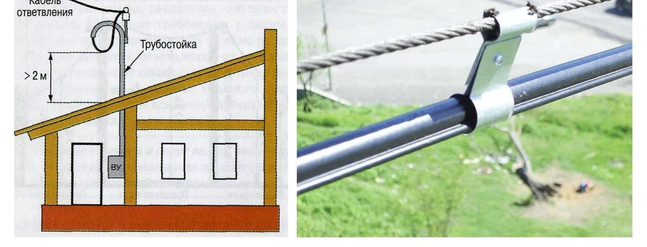
Cable inlet through the air is made in cases where the distance between the house and the substation is too large. For this, a cable with a supporting cable is used, which is stretched between the supporting and residential buildings. If the distance from the pillar to the house exceeds 20 m, then an intermediate support is installed between them.
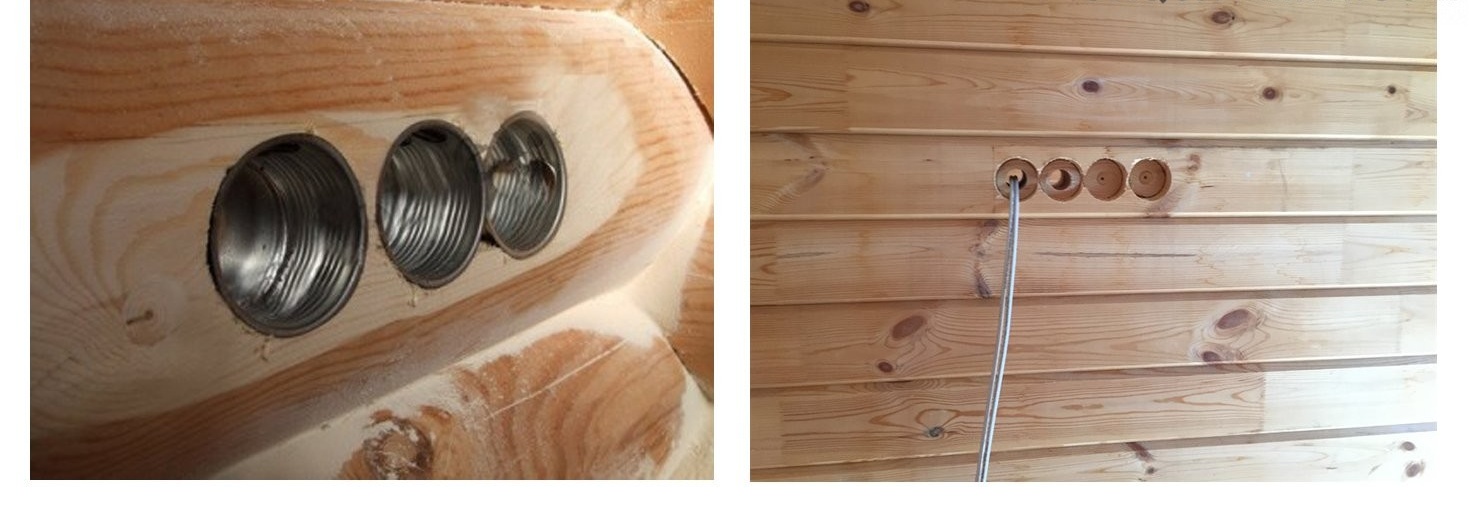
When a power cable is inserted through a load-bearing wall, a sleeve of non-combustible materials is installed at the interface. Optimally, if the cable is inserted in the immediate vicinity of the location of the switchboard.
Installation of overhead switches and sockets
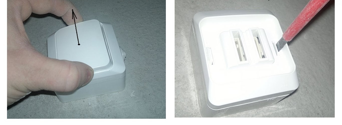
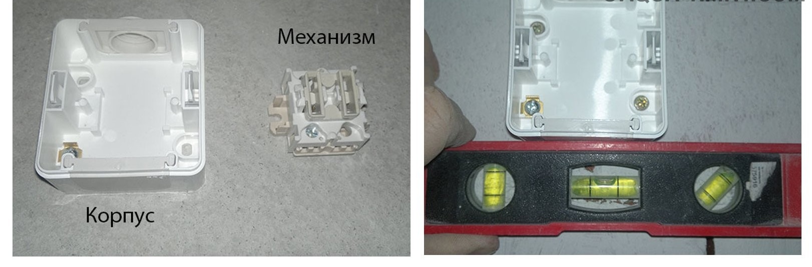
Removing the button and front of the outlet before installation
Overhead switches and sockets are used both with open and hidden method of wiring. The installation technology of the circuit breaker and the socket is similar, therefore, as an example, take the installation process of the circuit breaker from Schneider Electric.
The installation process consists of the following:
- Gently take out the switch key. To do this, take the edges of the keys and pull it towards you.
- Carefully remove the front panel of the product. To do this, squeeze the plastic clips along the edges of the switch and remove the panel.
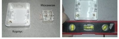
Dismantling and mounting the wall outlet using wall plugs and nails
- Under the front panel there is a switch mechanism, which is easily removed from the housing with a screwdriver.
- To attach the switch, we apply the back of the product to the wall, align it according to the level and apply markings for the fasteners.
- We drill holes in the wall using an electric drill. After we fix the case using the dowel-nails.
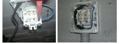
“Phase” and “Zero” Connections to Outlet Terminals
- The cable is inserted into the switch through the plug in the upper part of the product. To do this, part of the stub is cut with a sharp knife.
- To connect the switch, you will need to skip the cable inside the case and strip its end by 8-10 mm.
- The white wire (phase) is connected to the terminal marked "L", and the blue (zero) cable is connected to the terminal marked "N". After connection, the cable is fixed by means of bolts on the terminals.
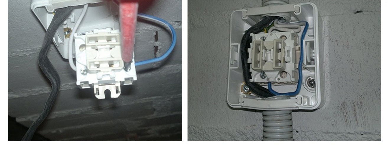
At the end, the operability of the switch is checked and the final assembly is carried out. The technology for mounting an overhead outlet is similar. As a rule, a three-core cable is used to connect the sockets, therefore, when connecting, there is a yellow-green cable (ground), which is connected to the central terminal.
Connection of wires and contacts
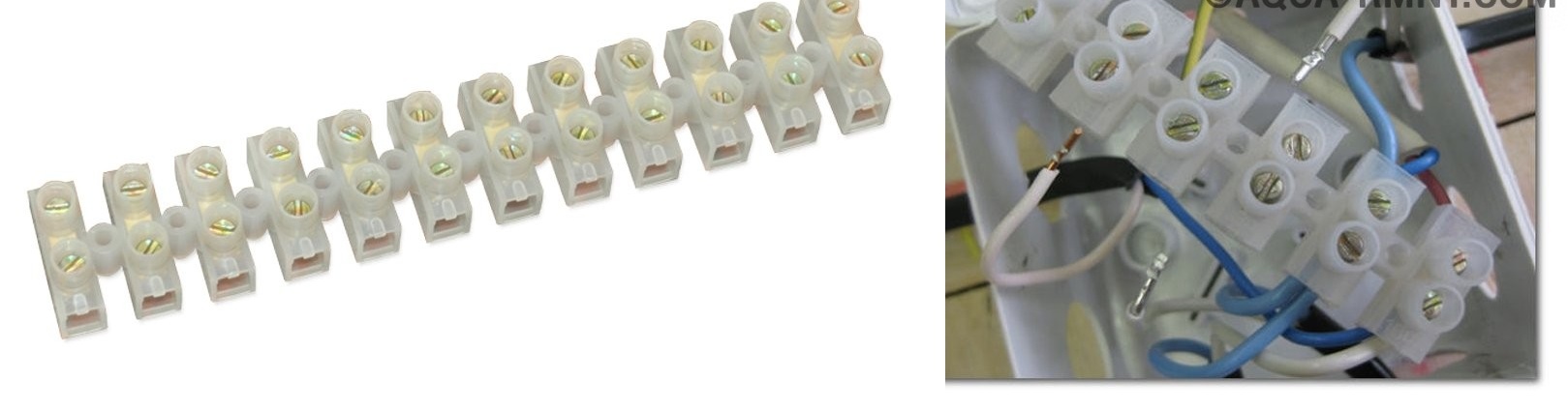
Terminal block with clamping screws
When installing electrical wiring in a wooden house, the use of "twists" is not allowed. Ideally, the part of the cable from the difavtomat to the point of consumption will be made of a single piece of wire.
To do this, before cutting the cable, it is necessary to mark the surface of the wall. Next, using a tape measure, you will need to measure the cable route and only after that cut the cable with a margin of 20 cm.
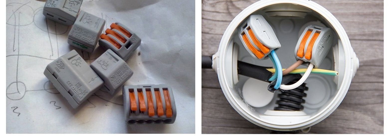
Wago terminal blocks for wiring
If a cable connection is unavoidable, then for this it is better to use:
- Terminal block - subdivide into products with a tightening screw and pressure plates.The latter are more optimal, since a plate is used to contact the cable and the bus, which does not damage the conductive core.
- The spring terminal is the simplest and most effective connection method in which the core is held and contacts the plate due to the spring clip. It can be used to connect both aluminum and copper cables.
When installing wiring in a wooden house, we recommend the use of terminal blocks from the company Wago. Products are of high build quality and have a wide range of products for cables of various sections. To connect, just strip the cable 10 mm, raise the clamping levers up and insert the cable into the terminal hole.
Ways to openly post wiring
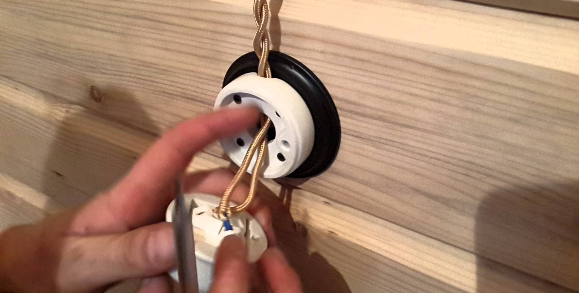
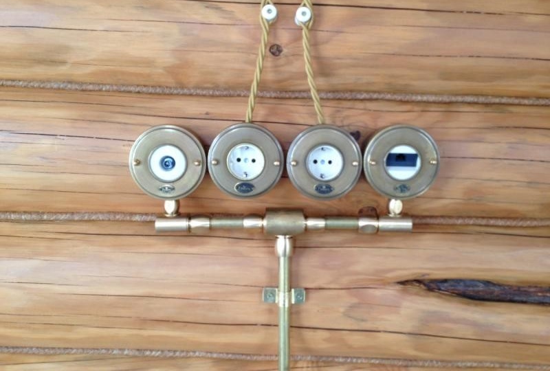
Covered retro wiring using ceramic sockets and insulators
Opening wiring is the best solution for wiring in a wooden house. An open way to lay the cable from the distribution panel to the point of consumption has been used for a long time - earlier the cable was located on ceramic insulators. Thus, the wiring did not have direct contact with a wooden wall.
Now this technology is called retro-wiring and is used in rooms where the total peak power is quite small and does not exceed 4 kW. In residential buildings with high peak loads, this technology has many disadvantages and limitations.
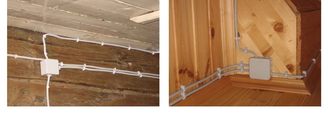
Open wiring in a wooden house without additional insulation
For an open wiring device, it is customary to use:
- An electrical conductor with a cross section of up to 6 mm2 can be mounted directly on the surface of the wall. To fix the cable, special clips made of non-combustible plastic are used. When choosing a cable, a person should give preference to products with a copper core having a double and triple braid. When using a cable with conventional insulation, the wiring is protected by a non-combustible gasket, which is fixed along the route and protrudes 8-10 mm on both sides of the conductor.
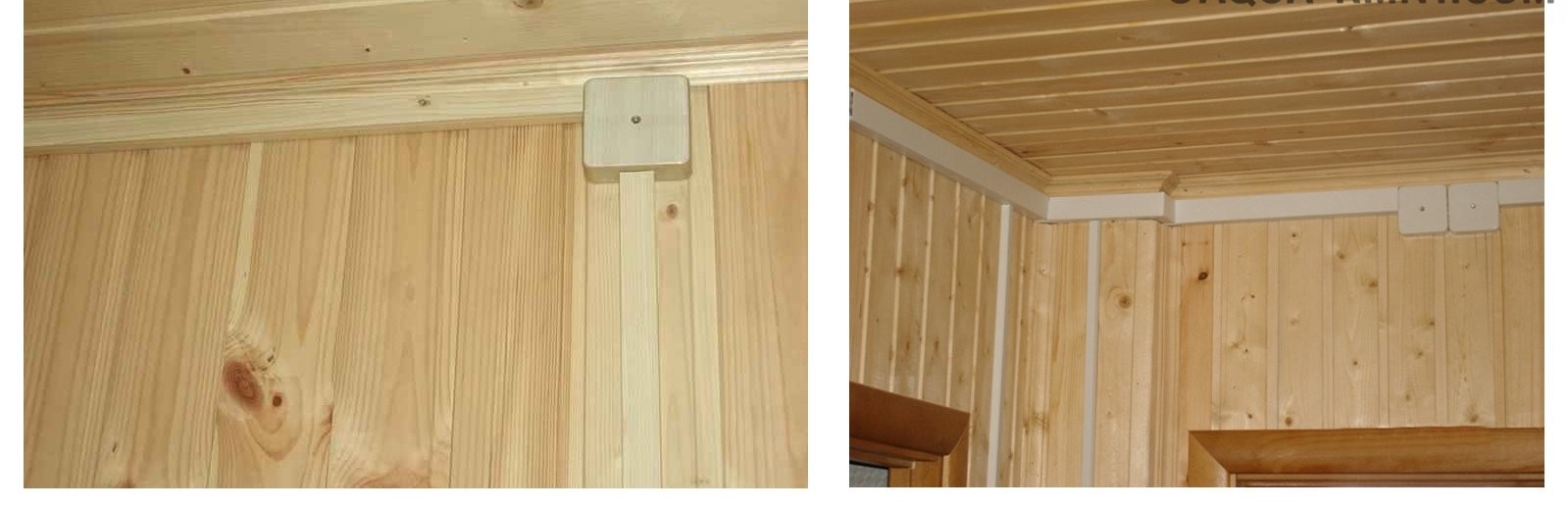
- Cable routing in polymer cable ducts. The cable channel is selected taking into account decorative and technical requirements. There are products for both single conductors and a group of parallel power lines. The cable channel is mounted on wood screws, and a plastic or metal front cover is used to protect the wiring. If repair is necessary, the cover can be easily removed.
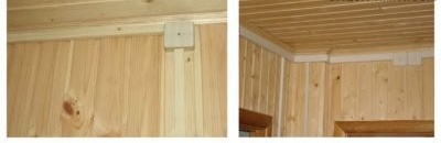
Open wiring in a wooden house in cable channels
- Electrical wiring in a corrugated metal pipe with diameters up to 2 cm. Several cables are placed in such a product, which simplifies wiring for soldering boxes and socket groups. The metal corrugation provides additional protection against mechanical damage. For laying, clips made of non-combustible materials are used, which create a 10 mm gap between the wall and the cable.
- Installation of electrical wiring in straight metal or polymer pipes. The technology is similar to the methods described above. The pipe provides good protection against cable overheating and fire, but during repair, you will need to completely dismantle the problem section of the wiring.
Some homeowners use a combination approach. To lay the cable in straight sections, a steel straight pipe is used, and metal corrugation is used as rotary elements. This approach cannot be called aesthetically attractive, but it is very reliable. For safety reasons, all metal pipes and other elements must be connected to the ground loop.
Related video: external wiring in cable channels
Hidden wiring in a wooden house
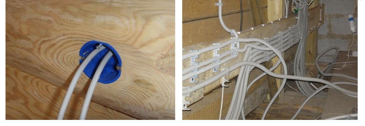
Installation of sockets and hidden wiring in a wooden house
The technology of hidden wiring in the arrangement of private housing has not gained much popularity due to the large amount of work that needs to be carried out in the process of laying the cable.Moreover, many homeowners do not want to sheathe the interior space, which is inappropriate for hidden installation.
In general cases, hidden wiring in a wooden house is carried out taking into account the following requirements:
- Wiring is placed in a fireproof enclosure. For example, it can be a steel pipe or a metal corrugation. In this case, the inner surface of the steel pipes must be galvanized. It is impossible to lay a bare cable without additional protection.
- The horizontal section of the pipe is laid with a slope to allow condensate to drain into the bottom of the pipe. If necessary, small holes are drilled in areas with an alleged accumulation of moisture. Rotary sections of the pipe are made of threaded elements that are connected by welding or soldering.
- Sockets for sockets and switches should be made of metal and connected to a ground bus. The place where the pipe enters the socket is reliably sealed. At the cable exit from the pipe, a special plastic plug is installed.
Grounding and installation of RCD

Preparation of a trench and installation of a grounding loop near a residential building
In addition to the grounding bus in the junction box, to ensure reliable protection of electrical equipment and household appliances with a metal casing, a full-fledged grounding loop will be required.
To do this, do the following:
- For the contour device, three reinforcement rods with a section of 30 and a length of about 3 m are required. A trench in the shape of a triangle with sides 1–1.5 m is dug under the contour. The pit depth is 30–50 cm. The reinforcement rods are clogged at the corners of the trench.

The place where the wiring is connected to the external ground loop
- To connect the rods to each other, you can use a steel corner 10 × 10 or 20 × 20 mm. The angle is adjusted in length between the rods and fixed for welding.
- A trench of similar depth is dug from the house to the contour. Optimally, if the trench will go to one of the corners of the contour. Next, a corner is laid in a dug trench and welded to the near corner of the contour.
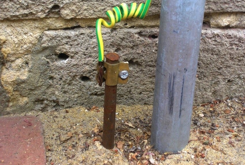
In the immediate vicinity of the house, a reinforcement rod of 50–70 cm is welded to the corner. It is ideal if, after backfilling, the reinforcement sticks out of the ground by 20–30 cm. At the end of the rod, a copper cable with a cross section of 2.5–4 mm is laid, which is laid in distribution panel and connects to the RCD.
In our next article, you will learn how to choose the right RCD for an apartment and a house:https://aquatech.tomathouse.com/en/ehlektrosnabzhenie/kak-vyibrat-uzo.html.
Installation Errors
The use of plastic teasers and PVC corrugations are the two most common mistakes when installing wiring in a wooden house
According to statistics, the majority of fires in wooden houses are caused by violations during the installation and operation of electrical wiring. Among the main errors are the following:
- Concealed wiring under the ceiling - laying the cable without additional insulation in the flooring in the immediate vicinity of wooden surfaces. If the cable cross-section is chosen incorrectly, this will lead to its rapid overheating and burning, which in this case is fraught with fire.
- Cable routing under the baseboard - a small space and contact of the cable with a wooden or plastic baseboard may cause it to overheat. The cable can be laid under the baseboard, but it must be a special design with 10-15 mm gaps.
- The use of corrugated PVC pipes - when installing wiring in wooden houses, the use of corrugated PVC pipes should be abandoned. It is better to replace them with free cable channels or corrugation made of metal.
- Laying the cable in the barrier without insulation - with a hidden installation method, the use of previously prepared pipes is allowed. But the cable must be laid in a metal corrugation or steel pipe.
As boxes for sockets and switches, only metal products that are securely connected to insulating pipes should be used. Plastic boxes do not provide adequate protection against overheating and can cause the spread of fire in case of fire in the wiring.
Wiring test

Measurement voltage with a multimeter
For testing electrical wiring, precision electrical instruments are used that are certified for use in electrical laboratories. During the test, the following work is carried out:
- visual inspection;
- resistance measurements on the insulation of the cable;
- resistance measurement on the grounding circuit;
- correct operation of the phase-zero circuit;
- RCD and automation tests;
- measuring readings on the device-grounding section.
Testing and commissioning of the power grid is carried out by the governing body, which filed an application for the electrification of the house. Upon completion of the inspection, the specialist confirms the correct operation of the electrical wiring in all areas. This gives a guarantee that the experts performed their work efficiently, and the consumer can use the power grid to safely spoil the equipment or cause harm to their health.
Related video: installation of hidden wiring in a wooden house
Electrification of a wooden house is a complex and time-consuming process, requiring the contractor to have the necessary qualifications and experience. If you decide to carry out these works yourself, then weigh the pros and cons. Even small omissions in technology can lead to serious consequences.

4 comments