Home-made heating distribution manifold: design instruction
Autonomous heating in a private house is good only when it is arranged rationally. However, it happens that the boiler is chosen suitable, and all the circuits are designed professionally, and the work is done strictly according to the technology, but there is still not enough heat in the house. Very often, to solve a problem in the system, a simple element such as a distribution manifold is missing. Making such a device yourself is not so difficult - in this article we will tell you how to do it.
Content
Why do we need a dispenser?
In a house with several heating circuits installed, a distribution manifold is a must. If we summarize the diameter of the inlet of each circuit and compare it with the diameter of the boiler connection pipe, it becomes obvious that the latter figure is much smaller. For example, a wall gas boiler nozzle most often has a diameter of ¾ inch. Let's say they connect to it:
- radiator system;
- underfloor heating system;
- indirect heating boiler.
The diameter of each consumer is 1 inch. Will the coolant have time to flow through an outlet of ¾ inch to three inputs of 1 inch? The answer is obvious: during the operation of such a system, it is quite natural that a coolant shortage occurs when all heating circuits are turned on at the same time.
For example, the radiator system is operating normally, but when the additional system of underfloor heating is turned on, a decrease in temperature is observed, the air in the rooms does not warm up. Simply put, hot water enters the system not fast enough.

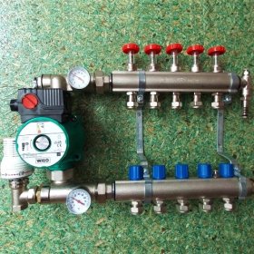
Distribution collector allows you to fully control the operation of the heating system of a private house and customize it to the specific needs and wishes of the owner
To solve the problem, you will need to install a distribution manifold. This is a special metal combon which a number of I / O devices are installed for each individual heating circuit. The collector allows you to adjust the volume of coolant entering the system, its temperature, pressure in the system, etc. With this device, you can centrally monitor the heating process of each individual room, equipped with its own heating circuit.
Through the distribution manifold connect:
- underfloor heating systems;
- radiator systems;
- converters;
- panel heating systems, etc.
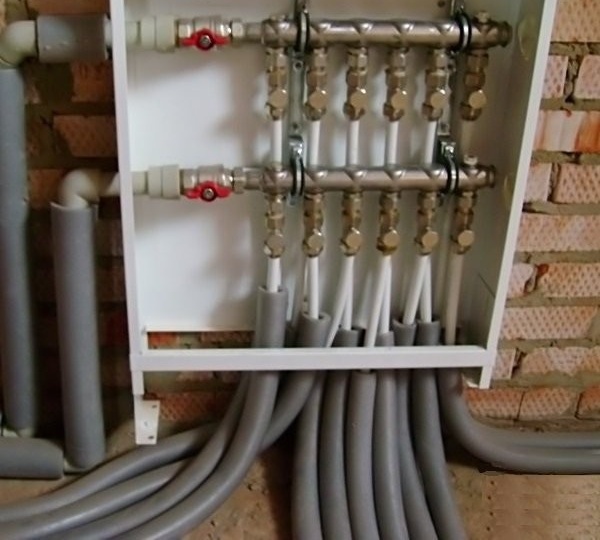
The distribution manifold has a supply and return sections, which are connected to each other. The supply collector allows you to control the actual flow of hot coolant to each specific heating circuit. This is very convenient, because in the event of a breakdown, you do not need to turn off the entire system, you can shut down only a separate circuit and make the necessary repairs.The return section of the manifold is necessary to regulate the pressure in a certain section of the system so that the quality of heating reaches a predetermined level.
Do not try to correct the situation by installing additional circulation pumps or special valves. They will not help to fill the heating system with a sufficient amount of coolant. But the distribution manifold copes with this task quite successfully. Please note that in a large house with two or more floors, it is recommended to use a separate distribution manifold for each floor.
Pay attention to the material, which describes in detail the principle of the collector heating system and its device:https://aquatech.tomathouse.com/en/otoplenie/razvodka-otopitelnoj-sistemy/kollektornaya-sistema-otopleniya.html.
How to make a collector yourself?
An interesting review of a home-made distribution manifold is presented in the video:
The manufacture of this useful device should begin with the drafting. In this case, the following data must be taken into account:
- number of heating circuits in the house;
- the number and characteristics of the heating equipment that will be mounted at the moment (boilers, boilers, etc.);
- the number and characteristics of heating equipment that is planned to be included in the system in the future (heat pumps, solar panels, etc.);
- quantity and characteristics of additional equipment.
Additional equipment includes:
- storage tanks;
- drain / fill taps;
- valves recharge;
- thermometers and manometers;
- security groups, etc.
After all these points have been taken into account, it is necessary to determine the connection dimensions for each group of pipes (feed + return), as well as for other elements of the system. Next, you need to understand the direction of each circuit. Pipes may enter the manifold from above, below, or from the side.
Solid fuel boilers and indirect heating boilers are usually cut into the ends of the collector. Gas and electric boilers are often mounted on the distribution manifold from above, however, if it is necessary to connect through a hydraulic arrow or with its own circulation pump, it is more convenient to cut such equipment from the end. Heating circuits are most often cut from above or below.
Now you can begin to draft the distribution manifold on paper. For this, a notebook sheet in a box and a simple pencil are quite suitable (lovers of high-precision projects can use a graph paper sheet). The distance between the contours can be arbitrary, the recommended spread is 100-200 mm (less or more will just be inconvenient). The distance between the supply and return of each circuit and the heating boiler can vary within the same limits. The device will look neater if this distance is the same for each circuit, which will allow you to visually highlight them.
If it is planned to connect mixing modules or pumping stations of industrial production, the distance between the supply and return in the project should correspond to the characteristics of a particular model.
On paper, you need to draw two long rectangles (these are the supply and return sections of the collector), then they indicate the feed and return. Now you need to use the ends of the device, for example, noting the connection of the floor boiler. Then the connection diagram of each heating circuit and all elements of additional equipment are successively indicated on the diagram.

The diagram clearly shows the project of a home-made distribution manifold for the heating system of a private house. It is necessary to indicate the names of all contours and indicate the diameters of the threads
In the process of drafting the project, it is recommended to immediately indicate the dimensions of all threads, as well as sign each contour and element to avoid possible confusion.
After the draft drawing is drawn up, checked and carefully thought out, it makes sense to take another sheet and redraw the diagram full. Now it becomes apparent the number of materials and devices that are needed for the manufacture of the collector, as well as the characteristics of these devices. You can make an estimate, purchase everything you need and prepare a tool.

In the manufacture of the distribution manifold, it is necessary to clean the metal from rust, apply precise marking according to the scheme and cut out all the necessary holes
A home-made collector will most conveniently be made of a square metal pipe. To do this, you must:
- Cut two pieces of metal pipe of suitable size.
- Cut pieces of a round metal pipe.
- To clean the metal parts of the future collector from rust.
- Make markup in accordance with the previously drawn up scheme.
- Cut out all necessary holes.
- Assemble the collector according to the scheme and grab the connection points by welding.
- Weld all pipes and threads.
- Weld the necessary fasteners.
- Strip all welds, removing scale.
- Degrease the surface of the device and paint it.
Before starting installation, it is recommended to wait a few days for the paint to dry. It remains to connect the finished collector to the heating system.

After the distribution manifold is assembled, it is necessary to scald all the joints, weld the threads and fasteners. At the end of welding, the seams are cleaned
Why is homemade better than the purchased option?
In heating equipment stores you can find a variety of models of ready-made distribution manifolds. Isn’t it easier to buy such a device so as not to waste time and effort? The fact is that the heating system of each house, especially the large house, has its own unique characteristics.

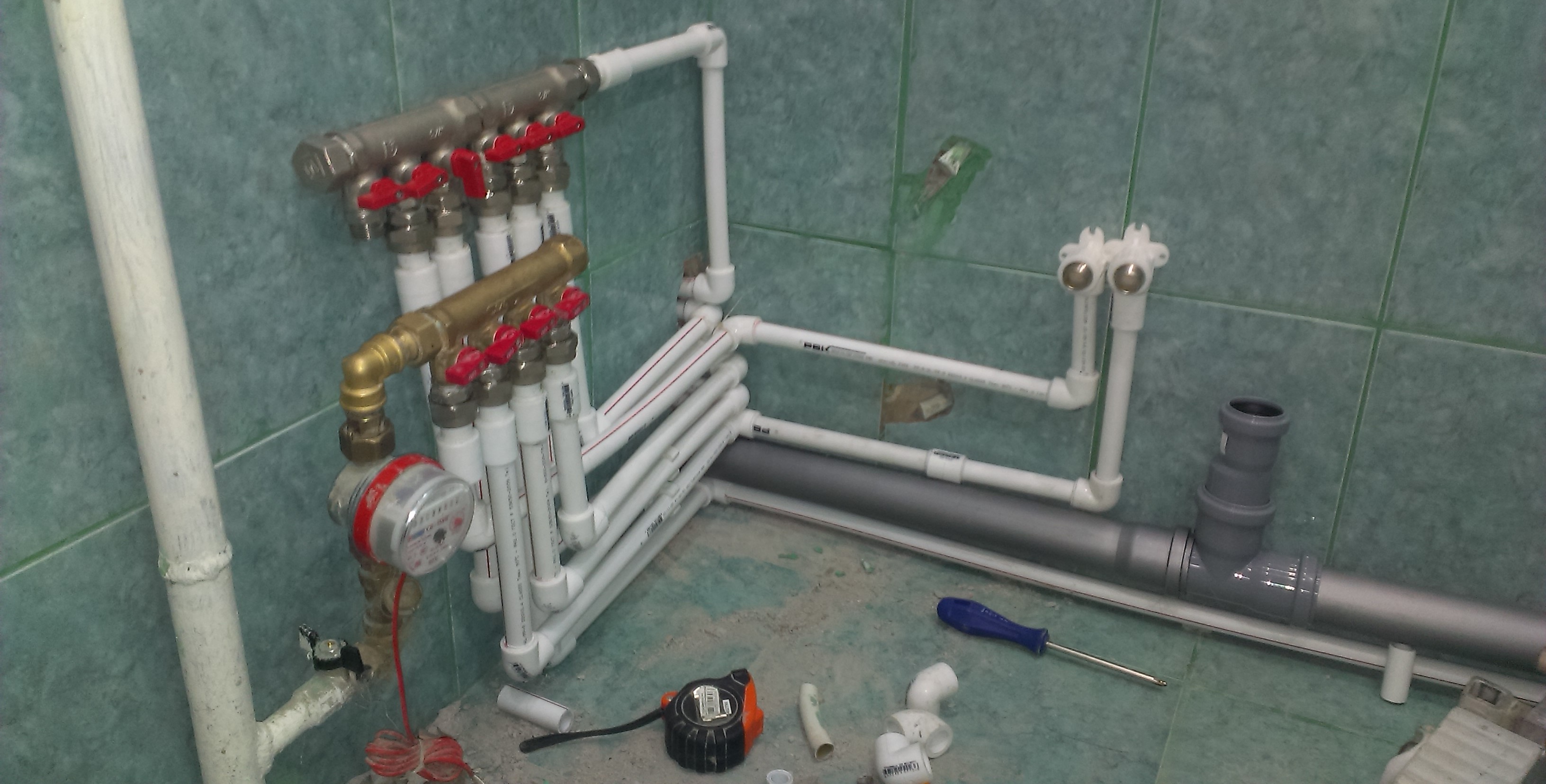
This is how a home-made distribution manifold looks like at the end of work and before painting. The cost of such a device is much lower than that of an industrial production model.
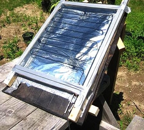
The solar heating system also uses the principle of the collector. For information on how to make such a system with your own hands, read our next article:https://aquatech.tomathouse.com/en/otoplenie/alt_otoplenie/solnechnoe-otoplenie-chastnogo-doma.html.
Often it is simply impossible to find a ready-made collector that fits perfectly, you have to install two collectors at the same time. It should be noted that the cost of a home-made device can be several times cheaper than the cost of one industrial collector, not to mention two.
Can the heating system work without a collector? Maybe, but not too good. In the end, the owner of the house, tired of the endless attempts to regulate the heating, meets the master and receives a professional recommendation: put the distribution manifold.
1 comment