Waste oil boiler with water circuit. DIY drawings and instructions
Liquid fuel burning furnaces have been known since the beginning of the last century. True, then they served mainly for the needs of industry. In everyday life, units operating on diesel or fuel oil were widely used in the years 60–80. It was at that time that oil products could be bought for a penny or even free of charge. Despite the significant increase in energy prices, it is also possible to heat your house cheaply now. We can say that the fuel for this lies simply underfoot, or rather, at every service station. The drained waste oil burns no worse than diesel fuel, and the workshop owners give it away practically for nothing. By the way, it is not necessary to buy a boiler for burning it. A simple and reliable unit with a water circuit can be built with your own hands, using materials that can be found in every owner.
Content
The device and principle of operation of a boiler using waste oil
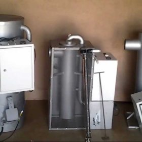
Home-made heating oil boiler
Merged automobile oils are multicomponent, highly contaminated substances, which also burn poorly. It can be said that, as a fuel mining, "not very" in itself, since oxygen is simply not able to oxidize all the chemical diversity that is in it. If you split the oil into simpler components, then burning them will be much easier.
The decomposition method has been known to modern science for a long time. Flame separation, or, in scientific terms, pyrolysis, is used to obtain simple flammable substances from any fuel - oil, coal, firewood, etc. This process is convenient because no additional costs are required for chemical transformations - for this enough heat, which is formed during the combustion of fuel. The advantage of pyrolysis combustion lies in the fact that this process supports and regulates itself, and therefore practically does not require outside intervention. All that is needed to start the decomposition process is to evaporate the fuel and heat the vapor to a temperature of 300–400 ° C. You can use two methods for this.
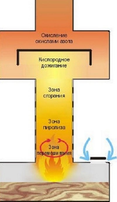
The processes occurring inside the furnace for development, provide high temperature and completeness of fuel combustion
In the first case, the fuel is set on fire in the tank, after which it begins to evaporate actively. Effective mixing and obtaining a uniform gas-air mixture is ensured by the Coriolis force, therefore, accurate calculation of the diameter and height of the combustion chamber is important. Fuel vapors rise along a vertical pipe with numerous openings through which they are saturated with atmospheric oxygen. In the upper part of the combustion chamber there is a partition, which is needed to reduce the gas velocity and to separate the zone of nitric oxide afterburning. It is in it that hazardous chemical compounds react with nitrogen oxides and decompose into harmless substances.
The so-called self-burn method, no doubt, has attractive simplicity and reliability, however, a tank with burning oil does not allow talking about safety. In order to eliminate this drawback, it will be necessary to complicate the design of the heating unit.
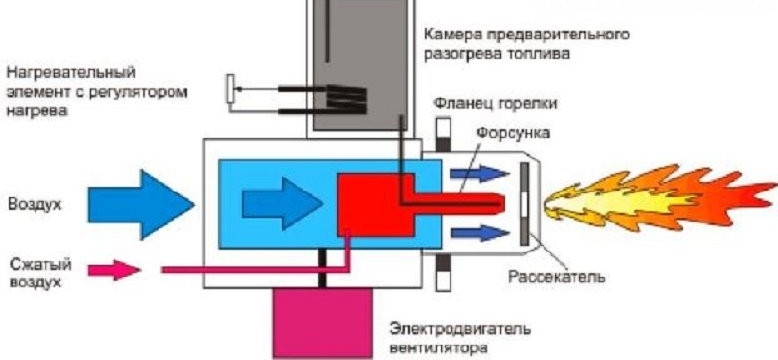
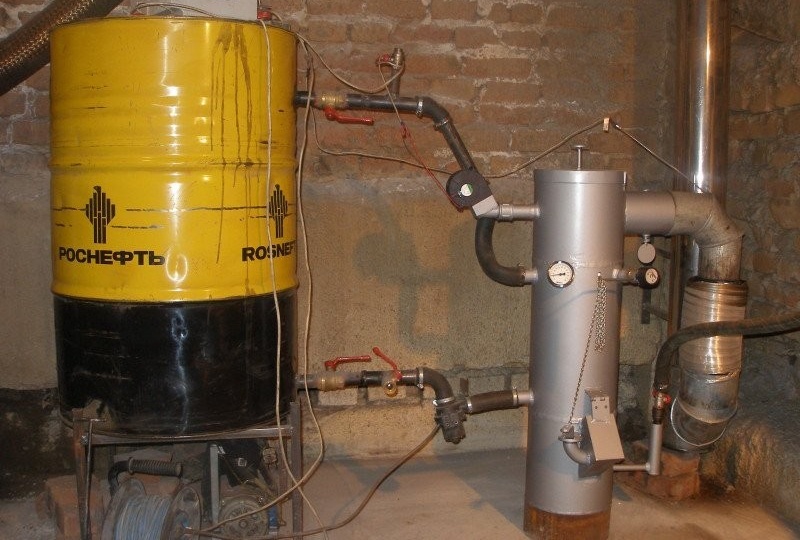
Mining combustion efficiency is significantly improved when using a specially designed burner
The second method involves the formation of zones of pyrolysis, combustion and afterburning directly in the flame, and for this you need a burner of a special configuration. To completely oxidize the fuel, the nozzle must provide a multi-stage formation of a gas-air mixture. In such a device, the primary movement of the fuel flow is provided by the compressor. Thanks to injection, the injected air carries atmospheric air along with it, and the formation of vapors occurs due to the heating of the burner by a flame torch. Practically the same processes can be observed during operation of a blowtorch. A similar method is implemented in industrial liquid fuel units. Homemade designs use the same principle, but work a little differently. In them, the mining drips into a red-hot tank, where it instantly evaporates and burns out at high temperature. In this case, one cannot speak of pure pyrolysis, since there is also the decay energy of molecules during microexplosions.
Read also our article on the manufacture of a stove-burner stove for waste oil:https://aquatech.tomathouse.com/en/otoplenie/bani-i-garazh/pechka-burzhujka-svoimi-rukami.html.
Types of structures under development
Depending on the application, boilers using used oil as fuel can be divided into three groups:
- household stoves;
- water heating units;
- heating boilers.
Domestic stoves are installed in rooms that for a number of reasons cannot be equipped with water heating. These units are characterized by reduced fuel consumption, and their design provides the most complete combustion of oil. Home appliances are virtually smokeless. In addition, furnaces are often equipped with emission cleaning systems, which increases the safety of their operation. The main advantage of units of this type is their mobility. The small size makes it easy to transport the stove and install it in a small room. It is also important that, if necessary, the device can be easily equipped with a water circuit or a platform for cooking.
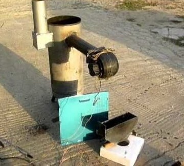
Household oil stove
Water-heating units at the level of the gas afterburning module have a special platform on which the water tank is supported. Its toroidal shape provides an additional advantage, since heating is carried out both from below and from the side of the smoke channel, which passes inside the tank. For autonomous water supply, a small water pump is mounted at the inlet of the boiler. Due to the high temperature, water can be heated much faster than in factory water heaters. For example, a 100 liter tank gains temperature from 20 ° C to 65 ° C in about two hours, while an electric or gas appliance takes twice as much time. If we talk about the cost of a standard liter of hot water, then when using mining, costs are reduced by 20–25 times.
The tank, installed at the level of the afterburning zone, turns the furnace at the end of operation into a powerful water heater
Heating boilers are used to connect to water heating systems, so they are equipped with exhaust gas afterburners, filters and safety devices. Despite all the safety precautions, it is recommended to install waste oil heating equipment in separate rooms or outbuildings.
Water heating in heating units is provided by a heat exchanger installed in the fuel combustion zone. It can be made as a continuous water jacket, or in the form of a spiral tubular contour. The movement of the heat agent in the system is possible thanks to the circulation pump, powered by electricity. The temperature control of the coolant is carried out by reducing the temperature of the flame. For this, the boiler is equipped with a forced air supply system. Reducing or increasing the speed of the turbine, regulate the flow of air into the combustion zone. Installing a thermostat allows you to automate this process.
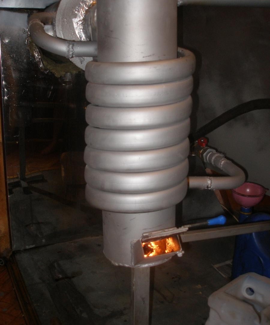
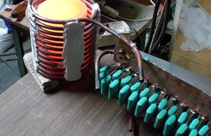
A boiler with a spiral water circuit will ensure the operation of the heating system of a country house
Often, units running on drained oil are duplicated by devices that use electricity, gas or solid fuel. This provides the functionality of engineering systems in the event of interruptions in the delivery of mining.
Pay attention to the material, which discusses options for garage heaters:https://aquatech.tomathouse.com/en/otoplenie/bani-i-garazh/kakoj-obogrevatel-luchshe-dlya-garazha.html.
Manufacturing a spent fuel boiler
According to the schemes described above, several types of boilers are developed and successfully operated. In addition, any solid fuel or gas heating unit can be adapted to operate on liquid fuel. Let's talk about the two most common designs that can be made independently.
Drawings of heating units
The drawings that we provide for your attention are tested on really working furnaces, so they can surely be used for your own projects.
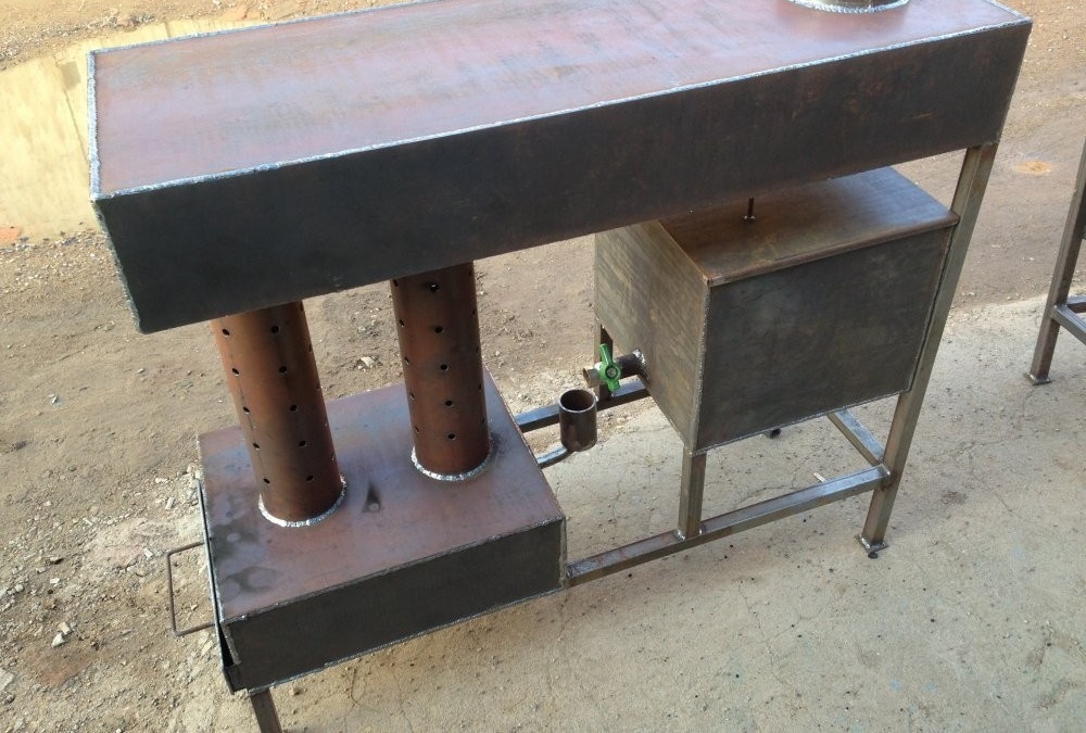
Two volume
This design consists of two cylindrical chambers interconnected by a piece of thick-walled iron pipe with holes for air penetration.
Drawing of a two-volume boiler with rectangular working chambers
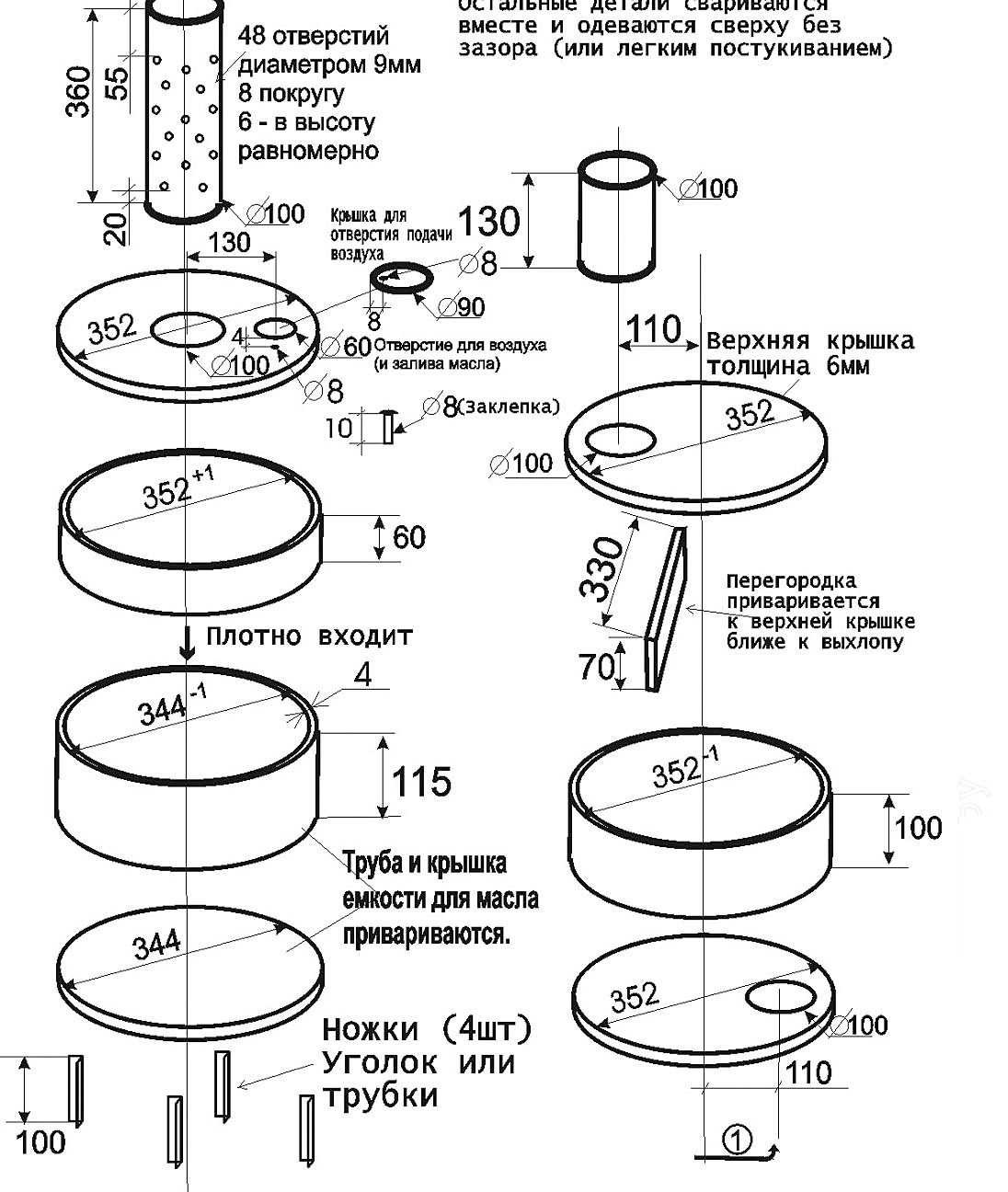
Drawing of a cylindrical double-volume boiler
The lower compartment is at the same time a fuel tank, an evaporator and a primary combustion zone. To fill the fuel, ignite and regulate the flow of air, a hole is cut out on its upper plane, which can be completely or partially blocked with the help of a rotary hatch. From below stove equipped with legs that ensure the stability of the structure and create a gap between its bottom and floor.
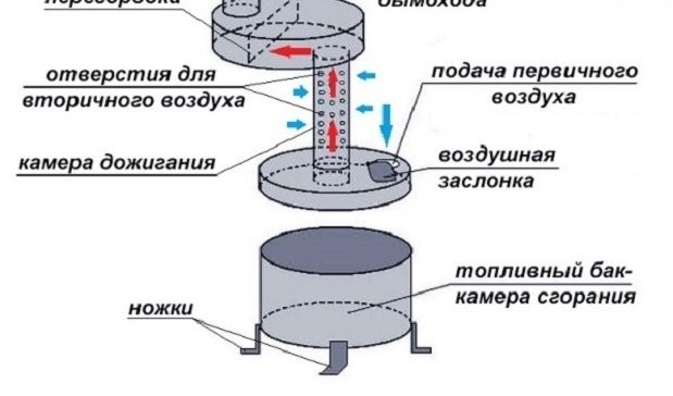
Diagram of a boiler with an open combustion chamber
A pipe with holes is welded into the upper plane of the furnace compartment. This hollow cylinder is a afterburner. The pyrolysis decomposition and combustion of the evaporating fuel (secondary afterburning) takes place in it. Almost the same capacity as the bottom is mounted on the upper section of the perforated pipe. The partition, which divides its internal space into two zones, reduces the rate of combustion products and ensures the completeness of their oxidation with nitrogen compounds. In addition, the upper chamber is also a heat exchanger that works as an infrared and convection heater.
A chimney mounted on the upper module creates the necessary draft and removes the residual combustion products to the outside. In order to secure the process of refilling the mining into the lower tank, a tube is connected to it, connected to a separate tank. The oil poured into the stove is set on fire with a rag soaked in gasoline or kerosene. After this, the air flow into the primary combustion zone is controlled by the flap.
By installing a water jacket or circuit on a vertical pipe, a boiler is obtained that can be successfully used in heating or hot water systems. At the same time, it is important to leave a gap of at least 50–70 mm to the perforated cylinder in order to ensure a free flow of air into the secondary combustion zone.
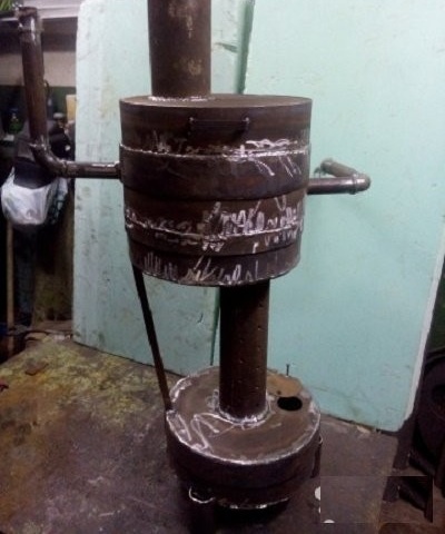
With a fiery bowl
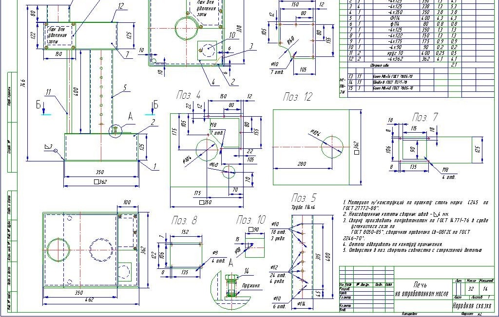
A simple boiler drawing with a fiery bowl is shown below. Its dimensions provide a thermal power of about 15 kW. In this case, no more than 1.5 liters of used automobile oil per hour is required. Air enters the combustion zone using a small fan or turbine. The supply of spent fuel takes place in portions, for which the tank with oil is equipped with a valve that can control the amount of fuel or completely stop its supply.
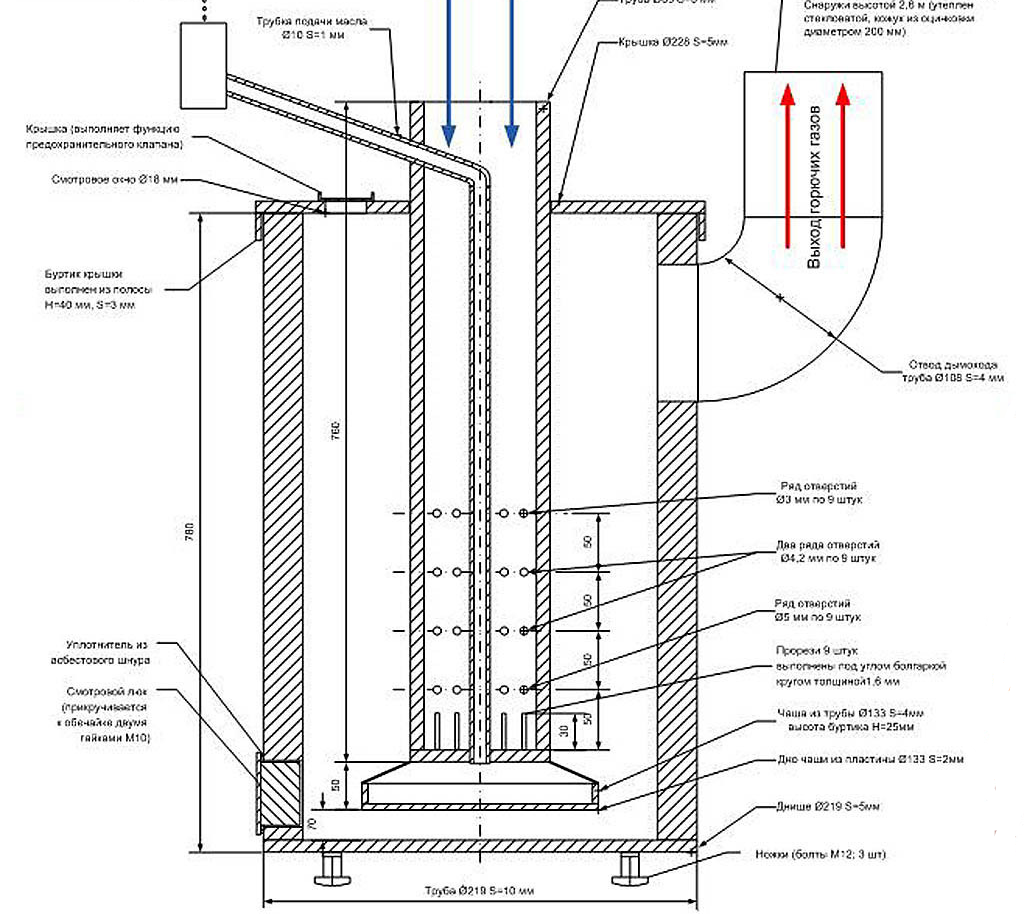
Flaming bowl boiler drawing
For afterburning of mining vapors, the central pipe is equipped with a system of holes and slots. Thanks to this design, the same processes occur around a flame bowl as in a two-volume furnace. Combustible gases are removed through a chimney mounted in the upper part of the combustion chamber. When arranging it, sharp turns and angles should be avoided, and the height of the chimney should be at least 4 m. This will provide traction sufficient to remove combustion products and ensure safe operation of the heating unit.
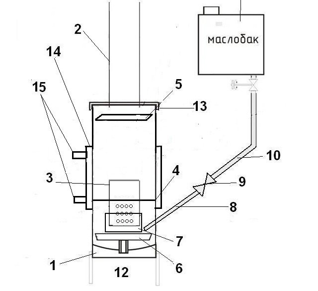
Scheme of a boiler made from a gas cylinder
The furnace with a fiery bowl is a closed device with forced air supply. This contributes to the safety of operation, and also makes it possible to easily and simply equip a water jacket. The diagram shows a working draft of the boiler described above, the housing of which can use a household gas cylinder.
Necessary materials
For the manufacture of a water heating boiler with a flame bowl, you will need not only a container for the manufacture of the casing, but also other materials (the positions in the diagram above and in the list correspond to each other).
- 50 liter propane tank.
- A metal pipe Ø100 mm with a thickness of 2-3 mm for the manufacture of a chimney.
- Iron pipe Ø100 mm 5-6 mm thick, which will be needed to make a burner.
- Steel sheet with a thickness of at least 5 mm to separate the combustion chamber and the evaporation zone.
- 3-4 mm thick metal sheet for manufacturing a visor designed to reduce gas velocity.
- Brake disc with a diameter of at least 20 cm from any car.
- The coupling (the same 100 mm pipe, only cut along its entire length) is 100 mm long.
- Ø15 mm steel pipe for oil supply to the bowl.
- ½ inch ball valve.
- Fuel hose made of oil-resistant refractory material.
- Tank for working out any type.
- Corner or steel profile for the manufacture of legs.
- Cover made of steel 4–5 mm thick.
- Steel sheet at least 3 mm thick for making a water jacket.
- Pipe fittings with Ø2˝ thread for connecting the boiler to the heating system.
Do not forget that to protect against corrosion and improve the appearance of the boiler, it will be necessary to paint, so buy a rust converter, primer, solvent and enamel for working on metal. In addition, to seal the joints, sealing materials will be needed - sanitary flax and special paste.
The shape, thickness and dimensions of the gas cylinder make it an excellent preparation for the manufacture of a boiler for testing
Tools for work
In the process of working on the boiler, you will need a variety of electric and manual bench tools. Here is a list of what you need to get from bins, purchase, or borrow from friends:
- welding machine - it is best to use a DC transformer unit or an inverter, since high demands are placed on the quality of the welds;
- electric drill and drill set for metal work;
- angle grinder and two discs - cutting and cleaning. Of course, these consumables should be designed for cutting steel;
- dies for threading pipes;
- electric emery;
- gas key;
- roulette;
- metal ruler;
- high carbon steel scriber for marking parts before cutting them.
Since you have to drill a large number of holes, you must definitely prepare a container with water to cool the tool. In addition, it is necessary to ensure the safety of welding, so it will be useful to stock up on a fire extinguisher.
You may also be interested in a material that describes the manufacturing process of a furnace for working out of a gas cylinder: https://aquatech.tomathouse.com/en/otoplenie/documents/pech-na-otrabotke-svoimi-rukami.html
Do-it-yourself boiler instruction manual
- Since even in an empty gas cylinder an explosive mixture of propane and air vapors can remain, you can cut it with a grinder or drill only after complete emptying. To do this, unscrew and remove the valve with a gas key. Then the container is turned upside down and the condensate is drained. Note that this liquid burns very well and has an extremely pungent odor, so work very carefully. After the liquid flows out, the workpiece is returned to its original position and filled with water through the upper hole - it will completely displace the remaining gas. After this, the liquid can be drained and any work carried out without fear of fire or explosion.
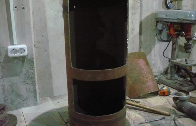
- Using an angle grinder, openings of a third of the diameter are cut out in the cylinder. If you measure around the circumference, then their length is 315 mm. The height of the bottom window is 200 mm, and the top is 400 mm. A 50 mm wide jumper must be left between the openings. The work must be done carefully, avoiding the displacement of the disk, since the cut metal sectors will go to the manufacture of hatches.

Prepared openings
Note! The increased size of the upper window is needed in order to transfer the boiler to solid fuel, if necessary. If there is no such need, then the lower opening will be enough. By the way, in this case, the installation of the casing of the water jacket is facilitated.
- To the hatch, which was obtained during the formation of the opening of the heat exchanger, welded hinges and a valve, after which the part is returned to its place.
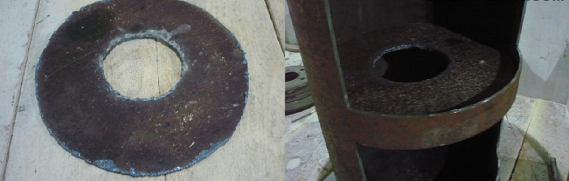
- From a 4 mm steel sheet, a ring is cut out according to the inner diameter of the cylinder, which is 295 mm. The hole that needs to be made in it must correspond to the outer diameter of the pipe for making the burner (in our case, 100 mm). This element will serve as a partition between the combustion zone and the heat exchanger.
Making the partition and fitting it in place
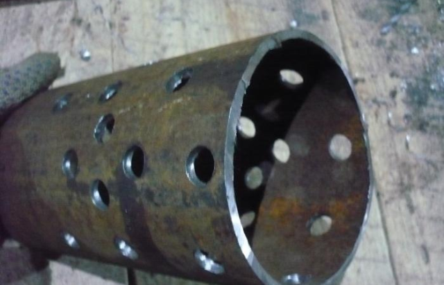
- A billet 200 mm long is cut from a thick-walled steel pipe Ø 100 mm.
- Drill Ø12 mm to a height of 95 mm in the lower part of the part. The distance between the holes should not exceed 40 mm - this will allow a more even distribution of the gas flow at the outlet of the burner.

The holes in the burner must ensure a uniform flow of burning gases in all directions
If the edges of the holes are carefully treated with a file, this will make it possible to do without cleaning them for a long time. This feature is associated with a decrease in roughness - particles of soot and dirt simply will not catch anything.
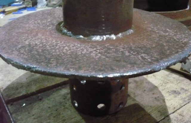
- The previously cut ring is mounted on the burner and welded directly above the holes.

Installing the baffle on the burner
- The partition is installed between the openings, at the level of the upper cut of the combustion chamber. Thus, in the lower part of the heat exchanger a step will be formed, which is necessary for holding the ash in the case of boiler operation on wood.
Installation of a unit separating the combustion chamber and heat exchanger
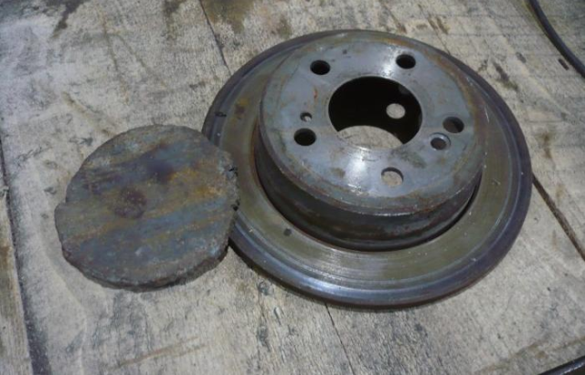
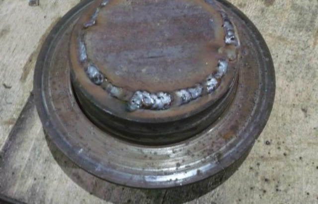
- Any thick-walled tank, preferably made of heat-resistant alloys, can be used to make the evaporator cup.The best for this purpose are cast-iron brake discs from cars. Technological holes in the workpiece must be welded. To do this, two round parts are cut from a steel sheet, one of which will be the bottom, and the second - with a cap. A hole is cut in the lid for the coupling and a window for supplying mining.
The holes in the brake disc must be plugged.
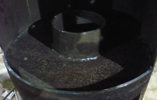
- A 150 mm piece of steel pipe is cut lengthwise with a “grinder”, after which the walls are slightly pushed apart, increasing the gap to 4–5 mm. This will allow you to remove the bowl to clean the remains of burnt fuel.

Welded bowl
- The bottom, the cover and the coupling are welded to the automobile disk, after which the assembly is mounted on the burner.
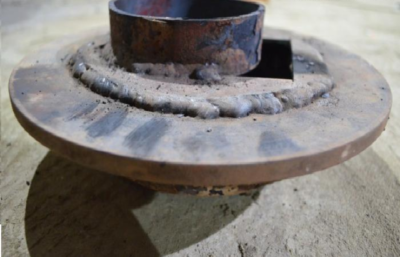
The coupling provides a tight connection of the bowl to the burner
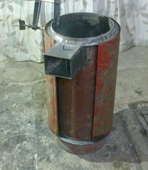
- A strip measuring 400x640 mm is cut out of a steel sheet, two half rings with an outer diameter of 305 mm and an inner diameter of 299 mm and two strips 30 mm wide. With their help, a casing of a water shirt is formed around the cylinder, scalding everything with a continuous seam.

Installation of a water shirt
- In the upper and lower parts of the casing, round holes are cut with a diameter of at least 40 mm and, using welding, the pipes for supplying and discharging the coolant are mounted.
- A boiler cover is made into which a chimney is inserted. Install the lid on the boiler.
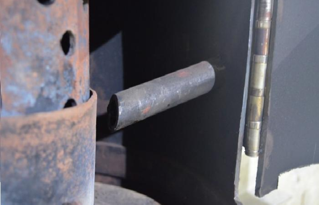
- A hole is made in the side wall of the container into which a fuel pipe is introduced at an angle. Its lower edge is cut at an angle, after which the resulting spout is installed above the oil supply window. After adjusting the take-off length, the fuel line must be welded to the boiler.

Fuel Line Installation
- Having cut a thread on a pipe for working off, mount a ball valve and attach a fuel tank.
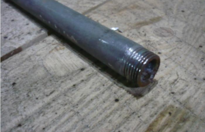
To connect a ball valve to the pipe, a thread is cut on it


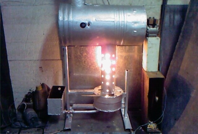
It is possible to carry out a functional check of the boiler without waiting for the insert into the heating system. To do this, pour the working out into the fuel tank and open the ball valve until the oil is distributed in a thin layer along the bottom of the disk. A small amount of kerosene is poured on top and set on fire. The fuel supply is regulated, being guided by the speed of its outflow and the level in the furnace bowl.
Video: Making a heating boiler from a gas cylinder
Strapping. Duplication of the furnace at the development of an electrical unit
Before connecting the boiler, you should consider not only the installation method and the placement points of additional devices and valves, but also the way the chimney is brought out. If it passes through a ceiling built using flammable materials, then a metal pencil case of twice the diameter is installed in it. The free space between the pipes is filled with asbestos or other non-combustible material with good thermal insulation properties.
Given the high risk of heating with liquid fuel, the installation of the boiler is best done in a separate room with good ventilation. The podium for the unit is concreted or covered with a metal sheet, which will protrude beyond its contours by at least 1 meter. After installation, the boiler is leveled and plumbed and only after that proceed with connection.
The simplest way to tie the boiler is to integrate into the gravity heating system. Despite its simplicity, its reliability is very high, since in this case there is no need for a circulation pump and automation devices. Nevertheless, the use of additional equipment allows you to accelerate the delivery of coolant to consumers and equalize the temperature at all points of the system, which saves fuel and increases comfort. For this purpose, a centrifugal pump and a membrane expansion tank are installed on the return line just before the boiler entrance. It is necessary so that the system does not depressurize with increasing temperature and pressure.A pressure manifold is connected to the upper branch pipe, and a thermostatic head or other regulating device (three-way valve, valve to reduce the supply pipe cross-section, etc.) is installed in front of each radiator to adjust the temperature of consumers. To remove air jams, an air vent is mounted at the top of the system.
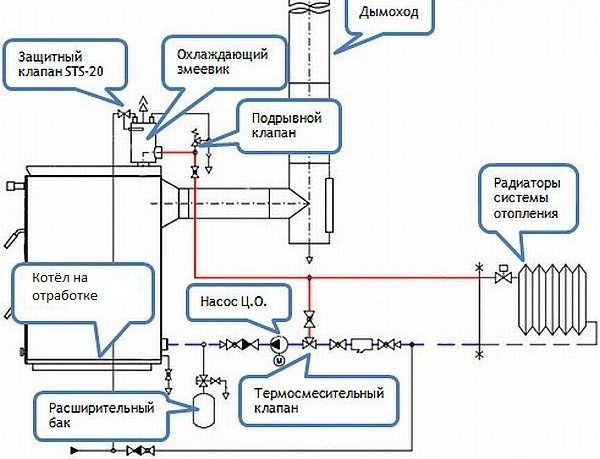
Wiring diagram for a waste oil boiler
The strapping of the unit working at mining requires taking into account the inertia of this type of equipment. In other words, the change in temperature of the coolant occurs gradually, therefore the unit necessarily equipped with a safety valve. It will allow to relieve pressure when it rises to a critical level. A good way to protect and equalize the temperature is to connect the indirect heating water heater in series. It will serve as the buffer that will take on excess heat in case of excessive temperature rise.
When connecting the boiler, shut-off valves are installed on the return and supply lines. This will make it possible to remove the unit for repair without having to remove the coolant from the system.
When they want to insure themselves against a shortage of used oil, an electric boiler is installed next to the home-made boiler. You can connect an additional unit in two ways - in series or in parallel. The advantage of the first method is that the coolant heated with the help of a flame bowl will flow into an electric boiler, which can be adjusted to a certain operation temperature. When the burner flame decreases, it will turn on and raise the water temperature to the desired value. The disadvantage of this method is the increase in the length of the main line, as well as the complete inoperability of the system in case of dismantling one of the boilers for repair.
Parallel switching implies the independent operation of two heating units and is characterized by the absence of these drawbacks. Unfortunately, this method is not without drawbacks, one of which is the need to install a hydraulic arrow and precisely coordinate the operating mode and feed the return line. In addition, fittings, pipes and fittings with parallel connection will go much more, which will certainly lead to an increase in cost and complexity of installation.
Despite all the disadvantages, in any case, the inclusion of boilers in a cascade helps to increase the reliability of the system. If we take into account that one of the units will periodically or regularly work on used automobile oil, then this will also save a lot of money.
Video: Automated operation of the unit with a water circuit
Today, burning used automobile oil is the cheapest and most affordable method of disposal. Unfortunately, this method is not the safest for the environment, especially with incomplete combustion of fuel. The fact is that the additives and additives that manufacturers use to increase the resource of power units are harmful carcinogens. The boiler that we offer for manufacture is designed taking into account the burning of mining at maximum temperature. This contributes to the complete decay of chemical constituents into safe substances. Therefore, getting started, be careful in calculations and listen to the advice and recommendations of specialists.
2 comments