How to connect a difavtomat according to the scheme and why is it necessary
The development of protection technology in electric networks for various purposes has led to the emergence of a convenient and practical device - a differential circuit breaker. The status of a practical device difavtomat deserves due to the combination of several protective functions. Unlike narrow profile devices used to provide protection against specific phenomena in the electrical network, difavtomaty provide comprehensive protective technology. The principle of operation and working conditions of the protection are described below.
Content
Why do you need a difavtomat in wiring
First of all, difavtomat is a protective device. Like a conventional circuit breaker, a difavtomat protects the part of the circuit on which it is installed from overload and short circuit. If such phenomena occur in the circuit, the difavtomat will disconnect the area under its protection similarly to a conventional circuit breaker.
In addition, the difavtomat is equipped with a function to protect a person from electric shock when a person accidentally touches live parts. In this sense, the difavtomat performs the function of an RCD.
Such a combination of the necessary types of protection makes the difavtomat suitable for installation and operation of electrical networks for various purposes.
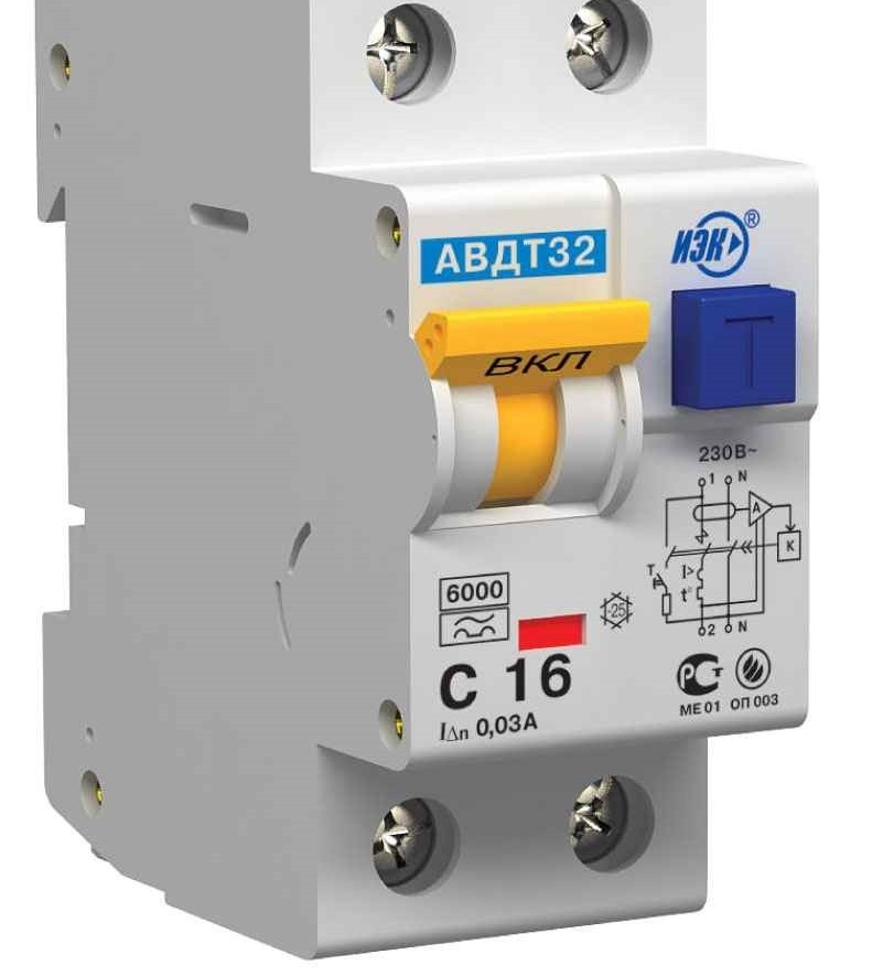
The versatility of this device is confirmed by its size, which did not particularly increase when combining the functions of two other devices. Difavtomat is installed on a din-rail similarly to other devices.
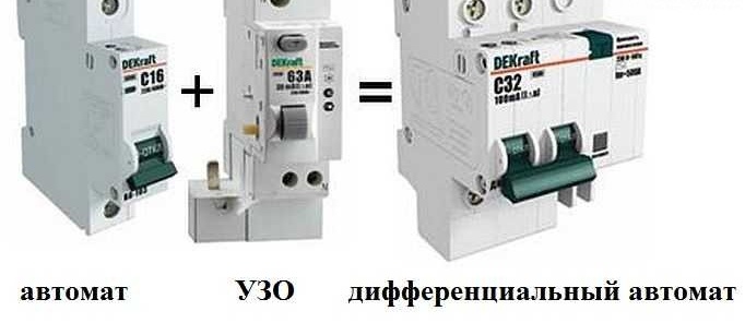
Combining the functions of an RCD and a circuit breaker
The safety and operability of the electrical network largely depends on the protection devices used. But the greatest value at all times remains human life. Protecting people who service and operate electrical networks should always remain a priority. In this sense, difavtomat is the optimal solution in the equipment of the protected power supply network.
With undoubted practical advantages, difavtomats are also somewhat more economical than a separate installation of an RCD and a circuit breaker.
You can read about the features of connecting a cross switch in this material:https://aquatech.tomathouse.com/en/ehlektrosnabzhenie/perekryostnyj-vyklyuchatel-dlya-chego-nuzhen-i-kak-ego-podklyuchit.html
The principle of operation and methods of operation
The principle of operation of the difavtomat also combines the principles of operation of a circuit breaker and an RCD. To protect against short circuit currents and overloads in the network, the difavtomat is equipped with electromagnetic and thermal trip units, and for protection against leakage currents it is equipped with a differential transformer and a trip coil.
In the event of a person falling under the influence of current on a part of the circuit protected by a difavtomat, a trip from the appearance of a leakage current will work. In the differential transformer, the balance of magnetic fluxes is disturbed and the trip coil will react to this instantly.
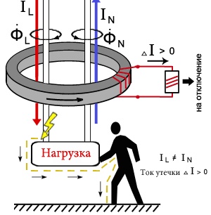
Leakage current
In the event of an overload of the electric circuit, the trip will be performed by a thermal release, which is structurally and nominally no different from thermal releases of conventional circuit breakers. And if a short circuit occurs in the current circuit, the magnetic release will perform its work, which also does not differ from the magnetic releases of circuit breakers.
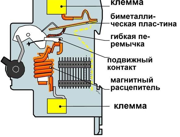
Location of magnetic and thermal releases
Depending on the installation scheme of the difavtomats, there are distinguished selective and non-selective actuation methods.
Selectivity is selectivity in the defense process. In the event of an accident, selective protection should disable the minimum number of consumers in the protected area.
As an example: in the event of a malfunction in a household appliance, the fuse should be activated in the appliance itself, and not in the switchboard of the entire building.
The selective scheme provides for the use of a difavtomat with the designation S on the front panel, which actually means “selective”.
The selective installation scheme is implemented by installing one difavtomat (selective) at the input (central distribution board, electrical panel on the stairwell, etc.) and several non-selective difvomatov in the outgoing circuit. One for each plot.
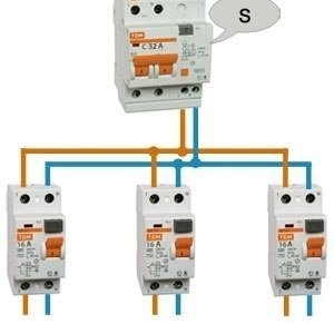
Introductory difavtomat and three outgoing sections of the chain
Such an installation scheme is preferable due to the fact that in the event of an accident in any of the three protected areas, disconnection will be performed by a non-selective difavtomat, and the main one will remain on. This method of operation provides a significant reduction in the risk of disconnecting all consumers at the same time.
The non-selective installation scheme is implemented similarly to the previous one, but with a significant difference. Introductory diflavomat not selective execution, but the same as the outgoing diflavomat. In the event of an accident on any of the sections of the circuit, the difavtomat, which protects this section, as well as the introductory difvomat, will be turned off, which, in turn, will turn off all consumer groups.
A functionally non-selective circuit performs protection correctly, but in terms of operation it is impractical.
Installation of a selective protection circuit is more preferable.
About the designation of sockets and switches on construction drawings and electrical diagrams can be read here:https://aquatech.tomathouse.com/en/ehlektrosnabzhenie/oboznachenie-rozetok-i-vyklyuchatelej-na-stroitelnyx-chertezhax-i-elektricheskix-sxemax.html
Connection diagram for differential circuit breaker
The connection diagram of the difavtomata is considered on the example of a 220 V.
The scheme can be implemented in different ways, depending on the budget and personal preferences in shaping the protection of the home electrical network.
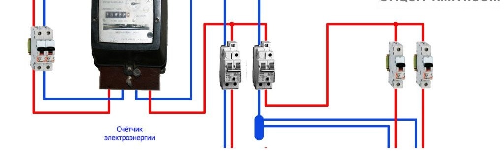
A relatively economical option involves the installation of one differential machine at the entrance to the apartment or house, and the installation of a conventional circuit breaker for each protected area. With this scheme, protection against overload and short circuit is carried out in each of the areas due to the operation of circuit breakers. And protection against leakage current is implemented in the entire circuit due to the differential input device.
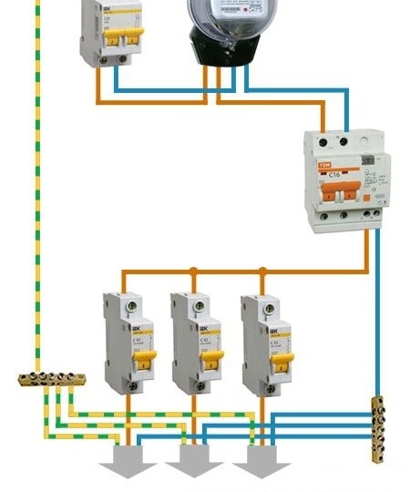
Connecting the input difavtomat in a 220V household network
The next connection option involves installing difavtomatov on each section of the chain. In this case, there is no need to install an introductory difavtomat. Each of the protected areas is provided with protection against overload, short circuit and leakage current. It should be noted that this option is more expensive than the previous one.Although more correct, from the point of view of the formation of protection, in the mains.

Diagram without an introductory difiltomat in a 220 V power supply network
The second variant of the connection scheme is preferable for rooms with high humidity. In such rooms, there is an increased risk of leakage currents to the ground due to the humid environment. To protect people, it is necessary to form a maximum protection against leakage currents. Installing difavtomatov on each group of electrical appliances will provide a high degree of protection.
How to connect
The connection diagram of the difavtomats in the 220 V network is considered above.
The connection diagram of the difavtomats in the 380 V network has significant differences. First of all, for such a scheme, a four-pole difavtomat is needed. Such a difavtomat is designed specifically for a three-phase network, has larger dimensions, but is also mounted on a din rail.
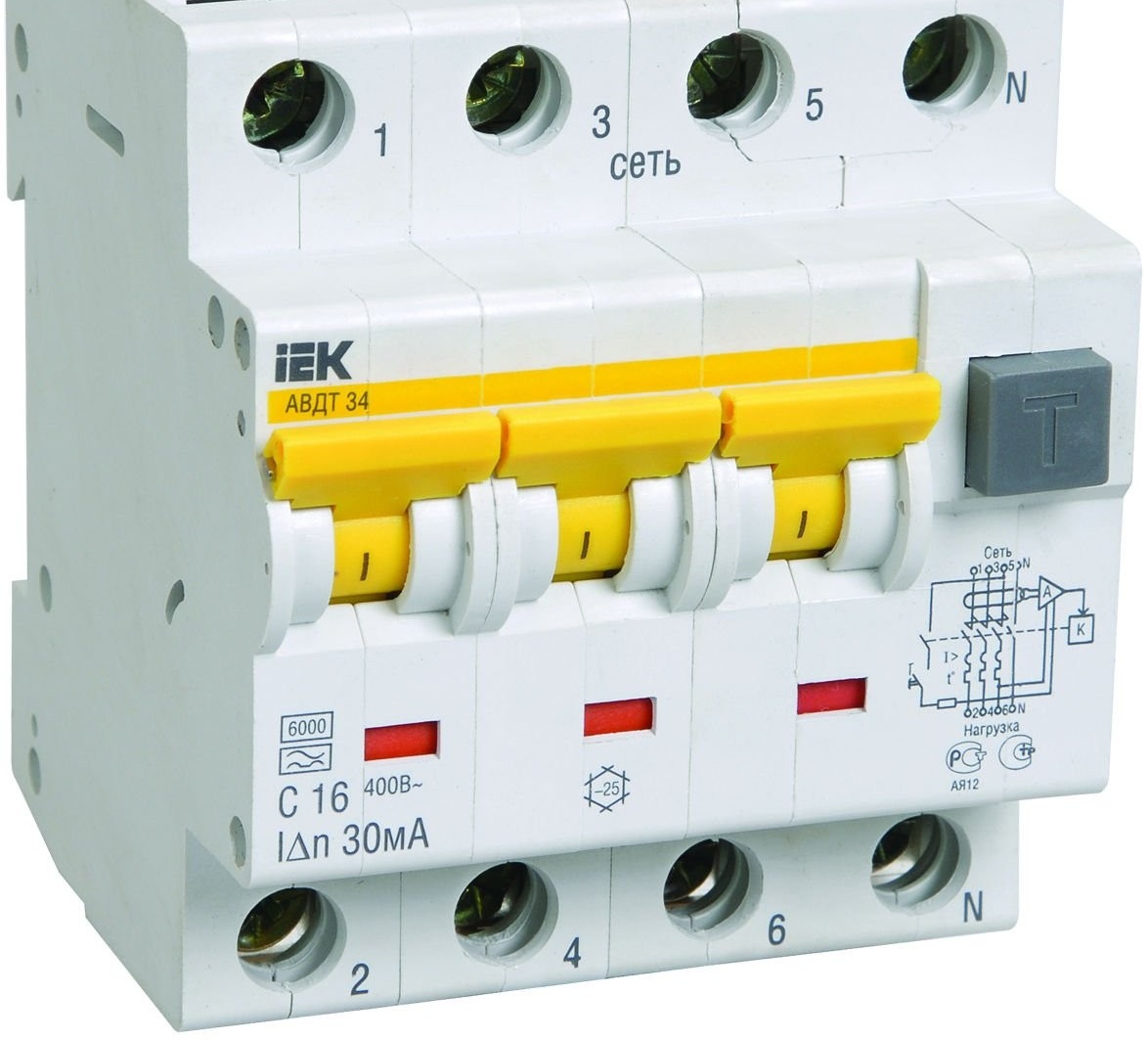
Three-phase version
The installation diagram of such a difavtomat provides for its installation after the counter. This type of installation can be implemented in a selective way, if the introductory difravtomat use selective execution.
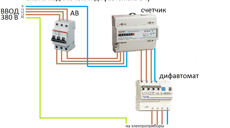
380 V network installation
In the absence of a grounding conductor in the power scheme of the room (home), the installation of a difavtomat is mandatory.
The most vulnerable spot of an incandescent lamp is a tungsten spiral, which is sensitive to sudden voltage drops. In order to smooth these cascades, special devices are used. Details:https://aquatech.tomathouse.com/en/ehlektrosnabzhenie/plavnoe-vklyuchenie-lamp-nakalivaniya-220.html
Protecting people from electric current above all.
The connection scheme in such a network is implemented as follows.
The simplest installation scheme in a 220 V network
With this scheme, the difavtomat itself will perform the function of a ground electrode system, instantly reacting to the appearance of a leakage current to the ground in the network. This will protect people using household electrical appliances or just being in a protected room.
Regardless of the type of electrical network in which the difavtomat is mounted, there are a number of rules that ensure correct operation:
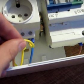
- The supply wires must always be connected to the device from above, and the downstream wires. Practically on all models of diflavtomats, the designation of the wire connections and the position of the input and output are marked. If the load is accidentally connected on the wrong side, you can cause an accident that causes the failure of the difavtomat. Sometimes you have to work in conditions requiring the installation of a difavtomat in an inverted position. This position will not affect the efficiency of its work, the main thing is not to mix up the connection terminals.
- It is important to observe the correct connection of the phase and neutral wires. In the standard international marking, the terminal for connecting the phase conductor is marked L, and the terminal for connecting the neutral conductor N. The incoming conductor is designated 1, and the outgoing one is 2.
- For the normal operation of the difavtomat, its neutral conductor should only be connected to its own circuit. It is forbidden to combine the zeros of all groups in a common chain.
It is important to remember that incorrect connection of the protection device will not always cause its breakdown. Incorrect connection will always not provide the proper level of protection and the correctness of its operation.
Video: device and device operating principle
Providing your living space with protection is always a hot issue. And providing protection for loved ones is even more relevant. Differential current circuit breakers help to solve one of the most important tasks - the problem of safe use of electricity. It is important that the solution to the issue is complex. This allows optimal use of installation tools, space and time spent on equipment protection schemes.