How to make electrical wiring and lighting in the garage with your own hands - diagram, cable calculation and installation technology
The presence of electrical wiring in the garage greatly simplifies the life of the car owner. In case of urgent need, you can quickly charge the battery or pump up a flat tire. And in case of serious breakdowns, the presence of lighting will allow you to carefully inspect the vehicle from the inspection hole. We have prepared for you instructions with diagrams that will allow you to do the installation yourself.
Content
Do-it-yourself wiring diagram in the garage
Single phase wiring diagram for garage
The garage belongs to the group of technical rooms, where open-type wiring is most often used. This allows you to carry out work on electricity in the shortest possible time. In addition, such a system is easier to upgrade and maintain. For safety reasons, wiring can also be laid inside the load-bearing walls, but if problems arise, the damaged area will have to be fully opened.
In garages used for parking and maintenance of no more than two cars, single-phase 220 V power supply with a frequency of 50 Hz is laid. This voltage is enough for the lighting, power outlet group, power tool, charging and start-up equipment.
Three-phase power supply voltage of 380 V is used only in garages used for the maintenance of a large number of cars and large-size equipment, when there is a need for constant operation of an electric boiler, power supply of machine equipment and welding machine.
Before carrying out installation work, a scheme for laying the power grid must be drawn up. To make a diagram it is better to use graph paper, which depicts the general plan of the garage, walls, floor and ceiling. All sketches are depicted in a reduced scale, convenient for applying the corresponding symbols.
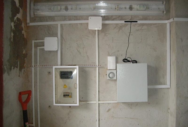
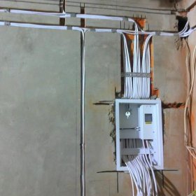
Example of external wiring in a garage
After that, the location of the following devices is indicated on the diagram:
- introductory switchboard;
- metering device, RCD, automation;
- rosette group;
- switches and lighting;
- power cable and wiring.
When plotting the circuit, it is advisable to consider the optimal location of the RCD, the meter, and calculate the route for laying the cable to the outlet group and lighting.The total number of outlets and lighting devices is determined, especially in the presence of a viewing hole.
When designing the wiring should provide a method of supplying electricity to the distribution panel, taking into account the location of the garage. Basically, the garage is being built in garage cooperatives with its own substation or near residential buildings connected to the mains. If you plan to build a garage in a separate area, then the method and route of laying the cable line from the nearest transmission line are calculated.
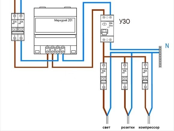
Scheme for a garage without a viewing hole
Single-phase garage wiring diagram for 220 V
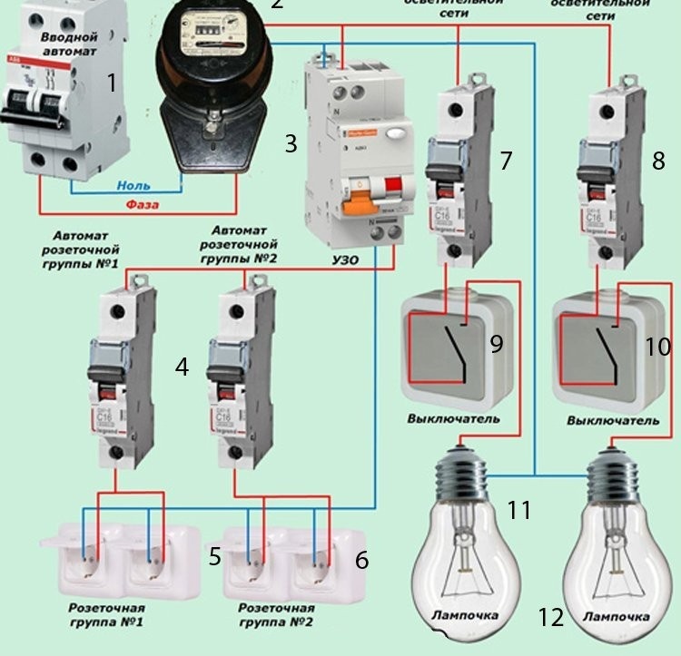
Taking into account the described conditions, the photo above shows a single-phase wiring diagram with a rated operating voltage of 220 V. This is an exemplary diagram drawn up for reference. In practice, especially with powerful equipment, the wiring diagram may have a slightly different look.
The diagram for a garage without a viewing hole shows:
- 1 - introductory bipolar machine, designed for 220 V;
- 2 - electric meter;
- 3 - RCD for the outlet group and lighting;
- 4 - single-pole machines for each outlet group;
- 5 and 6 - pairwise socket groups;
- 7 - automatic lighting system;
- 8 - automatic local lighting network for spotlights;
- 9 and 10 - switches for general and local lighting;
- 11 and 12 - lighting devices.
According to this scheme, a three-wire wire is used for wiring: phase (L), zero (N) and ground. The ground wire is designed to protect a person from the effects of electric current and maintain the health of electrical appliances. In order to simplify the circuit, the ground wire (PE) wiring is not shown.
Wiring diagram for a room with a viewing hole
Single phase garage wiring diagram with inspection hole
Conventionally, a viewing hole can be attributed to the basement located below the floor. According to the rules of electrical installations (PUE), an extra-low voltage current of 42 volts or less should be used to power the inspection pit.
To do this, a special transformer is mounted, which reduces the voltage and is designed for a total current power of up to 2-3 kW. In this case, equipment, power tools and lighting devices that are planned to be used when working in the inspection pit must be designed for this voltage.
It is not recommended to neglect this rule, as if a network malfunction occurs, you can get a serious electric shock, even death.
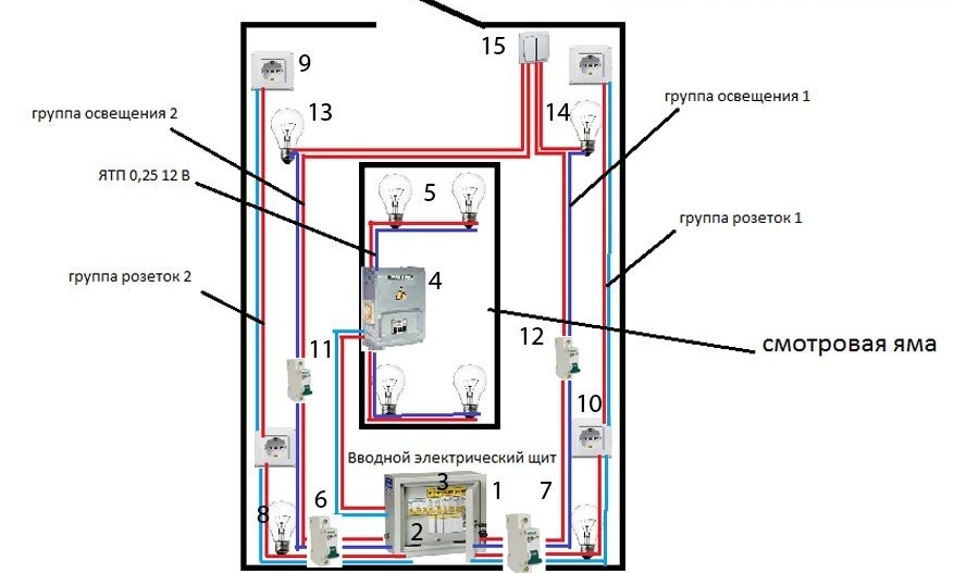
Above is the wiring diagram for the garage with a viewing hole. The diagram shows:
- 1 - introductory electric shield;
- 2 - introductory bipolar circuit breaker for 220 V;
- 3 - electric meter;
- 4 - step-down transformer to 36–42 volts;
- 5 - lighting pit;
- 6 - RCD;
- 7 and 8 - machines of the outlet group No. 1 and 2:
- 9 and 10 - outlet groups No. 1 and 2;
- 11 and 12 - automatic lighting group No. 1 and 2;
- 13 and 14 - lighting group No. 1 and 2;
- 15 - switch or several switches for lighting groups.
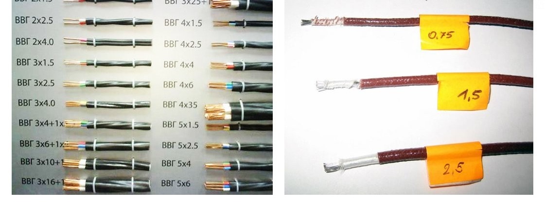
As in the previous case, a cable with a grounding conductor is used to lay the electrical network. For lighting, a cable is used - VVG 3 * 1.5, and for outlet groups - VVG 3 * 6. For sockets, the cable section is increased due to the ability to connect powerful equipment: compressor, welding machine, start-up device.
Video: charting tips
Necessary materials
A correctly designed wiring diagram will help to quickly calculate the number of cables, automation, outlets, etc. First, the cross section and length of the input cable are calculated. To do this, you can use the special table below.
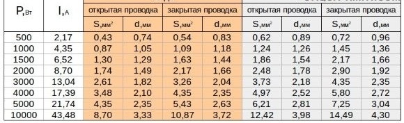
Table calculation of cable cross-section depending on the network power
For example, we calculate the parameters of the cable and other components for circuit No. 1, which was indicated in the last section:
- Cross-section of the input cable - in this case, a full-time workshop is not planned in the garage, so a copper cable of 4-4.5 square meters is ideal. mm
- Electrical shield - enough shield for 9 modules.
- The cable section for the outlet group - the power of the tool used to service and repair the car, rarely exceeds 3 kW. With this in mind, the cable cross section is selected - 1.5–2 mm. sq., but for safety reasons it is recommended to use a copper cable with a cross section of 2.5 mm. sq.

Cable for various sections
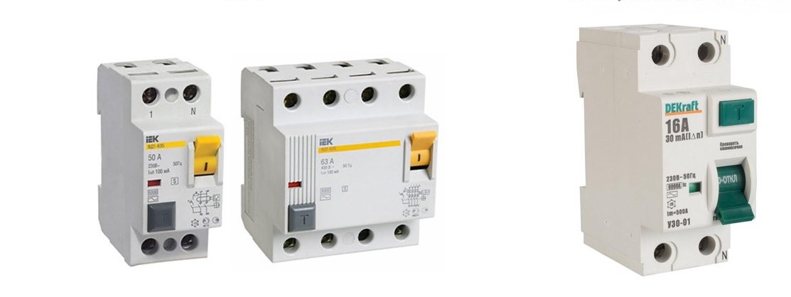
- Automatic machines of the outlet group - to select an automatic machine, the current strength should be calculated: I = P / U, where I is the current strength (A), P is the load power (kW), U is the mains voltage (V). Based on our data, it turns out that I = 3000/220 = 13.65 A. It turns out that for each group of outlets you need one modular machine for 16 A.
- RCD - a device for a passing current with a power of at least 20 A. The response current at which the device turns off is strictly 10-30 mA.
- Sockets - rated for a rated current of 16 A with grounding.
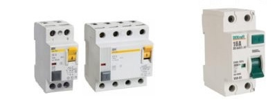
RCD and circuit breaker for mains
- Cable section for the lighting network - calculated taking into account the total power of the lighting fixtures. For example, on the ceiling there are two lamps with a power of 100 W, on the walls there are two lamps with a power of 60 W each. As a result, it turns out that the total power of the devices is 220 watts. For this power, an aluminum cable with a cross section of 1.5 mm is enough. sq.
- Automatic machines for lighting - the total current power is not more than 400 watts, even if you put ordinary bulbs of 100 watts in each lighting fixture. With a correctly selected cable section, a 10 A single-pole circuit breaker is enough
Cable length is determined based on the optimal route. The cable is purchased with a margin of 10%. It is highly recommended not to buy very cheap products. Optimally, if it is a wiring with double insulation and insulating conductors.
Necessary installation tools
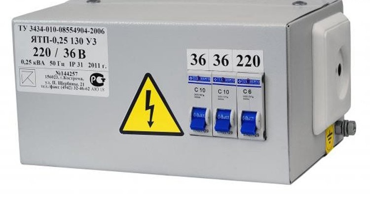
Step-down transformer for mains from 220 to 36 volts
To install the wiring you will need the following tool:
- pliers and side cutters;
- Phillips and slotted screwdrivers;
- hammer and chisel;
- electric drill and hammer drill;
- grinder with a disk for concrete;
- electrical tape and indicator screwdriver.
It is desirable that the handles of a hand tool be made of rubberized materials. If the handle is made of plastic, then before performing work it is necessary to wrap it with electrical tape in several layers.
Do-it-yourself wiring in the garage - step by step instructions
The installation of wiring and lighting in the garage consists of several stages: preparing the walls, pulling the input cable, installing internal wiring, connecting lighting and sockets.

Indicator screwdriver for checking the power at the contacts
When working with electricity, the safety rules must be followed:
- Connection, broaching, installation and other work are performed when the electricity is off. It is better to verify this yourself - carefully check each contact with an indicator screwdriver. To do this, the tip of the screwdriver is applied to the contacts and other surfaces, while the index finger is always in contact with the end face of the handle.
- When the switchboard is de-energized, a sign is hung on it: “Do not turn on! Work is underway. ” If it is not possible to completely de-energize the shield, then the connection should be carried out only with rubber gloves, standing on a rubber mat.
- Touching two contacts at the same time is prohibited. When working with three-phase wiring, you should be extremely careful. The voltage between the conductors in the 380 V network is much higher than in the standard 220 V. It is also important to remember that the effect of interphase voltage, especially when the current passes through the heart, is fraught with death.
If before performing work you are unsure that you can finish the job with due care and concentration, then do not proceed with the installation of the wiring. It is better to call a professional who will do the job more efficiently and with minimal risk to health.
Preparatory work
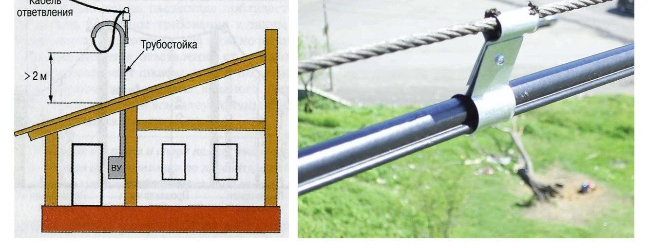
Pulling the power cable "over the air"
Before installing the wiring, prepare the cable and walls for laying communications. The cable is cut with a margin of 10 cm per connection. Before cutting, the wall surface is carefully measured according to the route built on the diagram.
Before marking, it is recommended to check the circuit once more for compliance with the following requirements:
- The cable route must go strictly horizontally or vertically. The turn of the track occurs only at an angle of 90o;
- wiring should be laid at a distance of 10-15 cm from the place where the walls mate with the ceiling or floor;
- switches are mounted at a height of at least 1.5 m. The distance from the doorway is at least 10-15 cm;
- sockets cut into the wall at a height of at least 60 cm from the floor surface. The distance between adjacent outlets is at least 4 m;
- for each group of sockets and lighting devices a separate circuit breaker is provided;
- for the inspection pit, a step-down transformer and lighting devices of the corresponding power are necessarily provided.
After that, marking is applied to the wall surface using a marking cord, marker or construction pencil. When using a pencil, the markings are checked by level. For this, a laser or bubble level is used.
If in the garage there are foreign dimensional objects and containers with combustible mixtures, then before laying the wiring they must be taken out to the street.
External wiring
Power cable pull “underground”
The complexity and scope of work on connecting the power cable to the garage will depend on the territory in which the building is located. If the garage is located on the territory of the house, then it is enough to dig a foundation pit of the required length and lay an armored cable.
For a building erected on the territory of a garage cooperative or being a separate building, you will need to submit an application to the organization that serves the power line.
Further, the organization will consider the application, documents of ownership and the drawn up power supply scheme. After which a decision will be made and requirements that the owner must comply with before connecting the power grid will be assigned.
According to SNiP, the power cable can be connected in two ways:
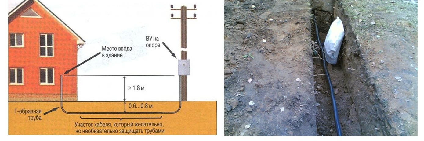
- Underground - a hidden way to connect a building using an armored cable. To lay it, a trench breaks out with a depth of at least 30 cm, below the freezing point of the soil. A 15 cm thick sand cushion is poured and compacted at the bottom of the trench. A corrugated pipe is laid on the cushion and the cable is pulled. After this pipe is filled with 15 cm of sand and finally walled up in the ground.
- Through the air - an open way to connect the building to the mains. For this, a cable with a supporting cable is used, which is pulled between the support column and the garage. If the distance between the garage and the pillar exceeds 20 m, then an intermediate support is installed between them. The height of the cable tension above the carriageway should not be less than 6 m above ground level.
Work on connecting the power cable is carried out only by a specialist of the management company. In the process of work, you have the right to control the progress and quality of their implementation. This is especially true for the depth of the cable - at least 70 cm and the height of the tension when entering the room - no more than 2.75 m.
Internal wiring in the garage

Wall chipping for electrical wiring
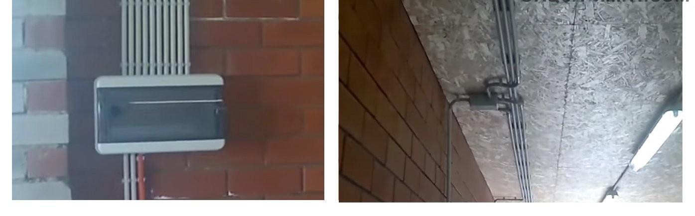
To enter the power cable into the garage, you will need to make a hole in the wall with a punch. The diameter of the hole is 20–30 mm.The cable runs through a corrugated PVC pipe with a cross section of 20–25 m and leads to the location of the electrical panel.
Further wiring inside the garage consists of the following:
- According to the marked markings, cuts are made to a depth of 2.5–3 cm using a grinder with a disc on concrete. After that, the concrete is carefully hollowed out with a chisel and a hammer until the cable channel of the desired shape is formed.

PVC corrugation for cable protection when laying communications
- In a pre-marked location, the electrical panel is installed on the required number of modules. For a single-phase network, as a rule, a shield for 9 modules is sufficient, and for a three-phase network - 12 modules or more.
- When installing the shield, you will need to carefully remove the packaging and the factory protective film. For wall mounting, unscrew the upper case and door. Under them will be the din rail for modules and terminals. All items must be temporarily removed.
- For mounting the shield in the wall, you will need to drill four holes and hammer in plastic plugs. After the back of the case is mounted on the wall using screws that are screwed into the mounting holes.
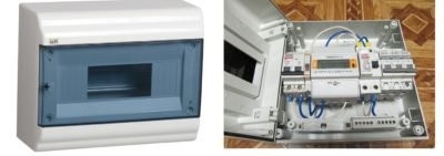
electric shield for the garage with automatic, RCD and counter
- Before installing the modules in the panel, it is better to mark them. To do this, you can use plain paper and transparent tape. The name of the module is written on a piece of paper 1 × 0.5 cm and glued to the product. For example, if several RCDs are mounted, then the first device is glued: "RCD of the outlet group No. 1".
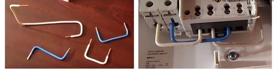
- After marking, the modules are mounted on the DIN rail in any convenient order, but it is better to start with an RCD and a counter, and then place single-pole machines. Next, the modules are connected using jumpers from a cable with a diameter of 2.5 mm. To do this, the wire is cut into pieces of the desired length. The end of the jumpers for connection to the machine is smoothed 1 cm, and for connection to the meter 2 cm.
- When connecting modules in a single-phase network, jumpers of white and blue color are used. The white wire is the phase, and the blue is zero. The top contacts are for connecting phase wires from the meter, and the bottom for outgoing wires to sockets and lighting.
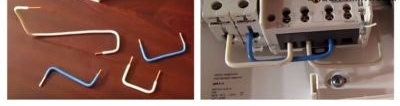
Staples from a wire to connect the machine and RCD
- After connecting the "phase" and "zero", it is necessary to connect the outgoing from the meter, RCD and automatic machines of the "zero" wire. To do this, the jumper is displayed on the contact terminals of the "zero" bus. Finally, carefully check the clamping screws.
- To connect the power cable, you will need to insert a protective corrugation with a conductor into the shield through a puncture in the product. The cable connects to the input box at the top of the device.
- Braided wire extends from the circuit breakers through cable channels or PVC pipes mounted on the wall. When connecting the line to the location of the outlets, a junction box is mounted. Installation is carried out open or hidden.
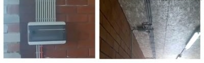
Mounting the switchboard on the wall and ceiling boxes
- With the open method, the box is mounted on the ceiling or wall using self-tapping screws. With the closed method, a recess is drilled in the wall under the box using an electric drill with a crown nozzle. Next, to connect the wires, a color-coded scheme is used, which is included. A line is drawn from the box to the outlet group and is connected.
- In a similar way, a line is drawn for lighting and switches. The cable extends to the location of the switch, where it is soldered and goes to the lighting fixtures.


After broaching and installing all the wiring nodes, the quality of the connection of the devices, the insulation and the connection of lighting are checked. If all work is performed taking into account SNiPa, then you can check by applying power.
Video: how to connect an RCD
Inspection pit lighting
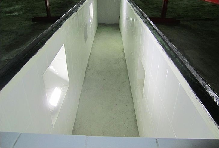
Lighting of a viewing hole in a garage with 36 volt lamps
Lighting and arrangement of outlets for the inspection pit, as a rule, is carried out only in garages, where it is planned to install three-phase wiring with a voltage of 380 V. For this, all the work described above is performed. In addition to this, a step-down transformer is mounted and connected near the switchboard.
A line is drawn from the transformer in a closed way - a wall is knocked out in the wall and floor where the cable protected by PVC corrugation is laid. After that, the cable leads directly to the inspection hole, where it diverges to the lighting group.
As lighting devices, low-voltage lamps 12–36 V based on LEDs are used. It is desirable that the lighting device was completely made of plastic. If there is a metal circuit or cover on the case, then it is additionally grounded.
Sockets and switches for lighting in the inspection hole must be located outside. It is optimal if they are located in the immediate vicinity of the switchboard.
Video: DIY wiring in the garage
Garage lighting with LED strip
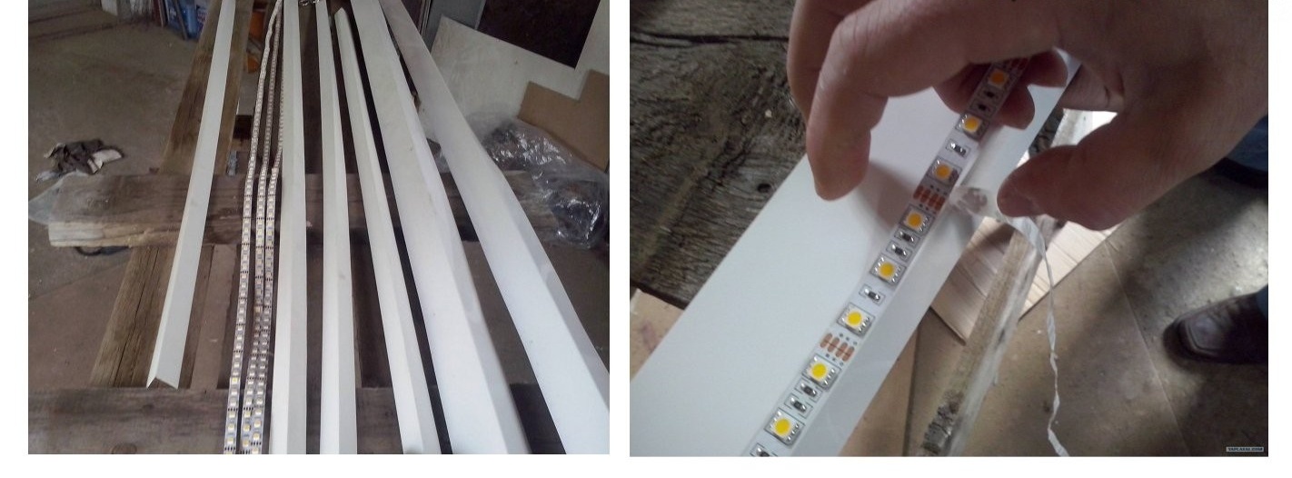
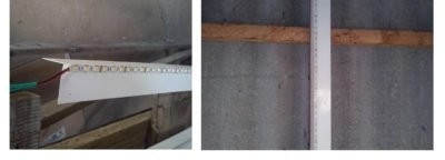
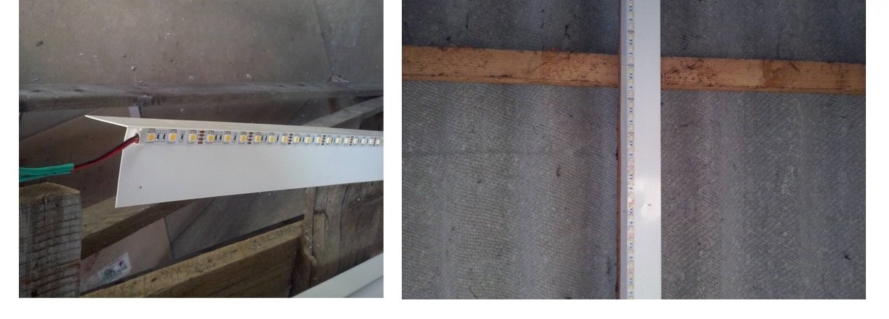
SMD 5630 LED Strip & Plastic Corner
LED strip is a modern and energy-efficient way of lighting rooms up to 30 m2. Especially in garages where the arrangement of general lighting is not required, but only the illumination of working areas is needed.
DFor contour lighting of a garage, the most commonly used type tape is SMD 3528 with a luminous flux of 5 lumens / diode. As central lighting, tapes of the SMD 5630 type with a luminous flux of 40 lumens / diode are used.
The technology for mounting and connecting the LED strip will consist of the following steps:
- For a garage up to 25-30 m
LED strip glued to the corner and fixed on the beam using self-tapping screws
2 you will need 10 meters of tape with 5050 diodes. The number of diodes is at least 60 pieces per tape. In addition, you must buy a converter from 220 V to 12 V with a power of 150 W and a cable for connecting the device to the network.
- The tape has a self-adhesive base, which is especially convenient when mounting the tape on metal or plastic surfaces. In the garage, you can use the plastic corner, which is screwed to the roof beams or concrete ceiling.
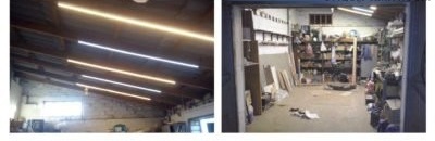
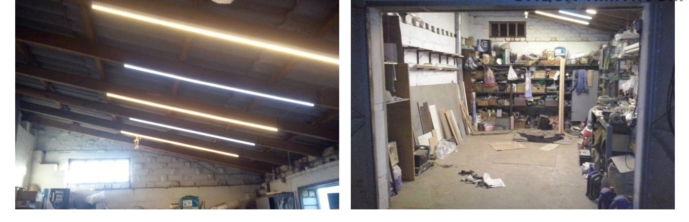
LED lighting in the garage after connection based on 5630 diodes
- Before gluing the tape, you need to determine the convenient length of the tape. Further, the corner is adjusted to the appropriate sizes. After that, the tape is cut to length and glued to the corner. Before gluing, the plastic surface is degreased.
- Thus, the required number of corners with ribbons is prepared. At the end of the tape, wires are soldered to the contacts and insulated with electrical tape. Then the corners can be mounted on beams or ceiling.
- Wago terminal blocks are used to connect the tape to the wire. Each wire is inserted into a separate socket in the product. A 2.5 mm copper section wire will extend from the terminal blocks.
The connection diagram of the tapes to the power supply is shown in the photo above. You cannot use serial connection of tapes. If you plan to install RGB tapes, you must use an RGB controller.
Installation of electrical wiring in the garage is a very time-consuming process, requiring appropriate knowledge and skills. Before starting work, carefully study all available documentation and read the safety instructions. If you are not sure that you can do the job, then abandon the plan and call a professional electrician.