How to make grounding in a private house with your own hands

All household electrical appliances not only make our existence comfortable, but also pose a certain danger to human health. Therefore, in a network of any voltage class (220 V or 380 V), it is always necessary to provide for the presence of grounding in a private house, we will describe how to do it later.
Content
Why grounding is needed
Grounding in the electric network is based on elementary physical laws and is a universal system for protecting a person from electric shock, and also a system for protecting electrical equipment of any purpose from insulation breakdown (grounding). Operation of electrical networks without grounding is potentially fire hazard. Equipping a private house with an earth loop is a prerequisite for the safe use of any electrical appliances and apparatus.
According to the rules for the installation of electrical installations (hereinafter PUE), which applies to all types of electrical installations, protective grounding must be provided.
1.7.56. To prevent electric shock if the insulation is damaged, the following protective measures should be applied separately or in combination in case of indirect contact:
-protective grounding (1.7.63, 1.7.65, 1.7.66);
- automatic power off (1.7.61, 1.7.63);
- equalization of potentials (1.7.78);
- equipment of class II or with equivalent insulation (1.7.86, 1.7.87);
- protective electrical separation of circuits (1.7.86, 1.7.88);
- insulating (non-conductive) premises, zones, sites (1.7.86, 1.7.89);
- systems of ultra-low (small) voltage BSNN, ZSNN, FSNN (1.7.68–1.7.70);
- equalization of potentials (1.7.65, 1.7.66).
For an objective understanding, you need to understand the following terms, according to the EMP:
- Direct touch - electrical contact of people or animals with live parts under voltage, or approaching them at a dangerous distance.
- Indirect touch - electrical contact of people or animals with an open conductive part that has become energized as a result of damage to the insulation.
- Direct touch protection - protection against electric shock in the absence of damage to the insulation of conductors.
- Indirect Touch Protection - protection against electric shock in the event of a single damage.
- Earthing switch - a conductive part (conductor) or a set of interconnected conductive parts (conductors) that are in electrical contact with the earth directly or through an intermediate conductive medium, such as concrete.
- Ground conductor - a conductor connecting the ground electrode to a specific point in the system or electrical installation or equipment.
- Grounding device - a set of electrically interconnected ground electrode and grounding conductors, including elements of their connection.
-
Grounding - making an electrical connection between a specific point in the system or installation or equipment and local ground.
Note. The connection to the local ground can be intentional, unintentional and random, as well as permanent or temporary.
Having made sure of the need for grounding, we can begin to consider the issue of independent equipment of a private house with a grounding circuit.
What types are there
First of all, you need to understand what kind of grounding you need to mount. The decisive factor in the decision will be the voltage class in a private house (220 V or 380 V).
There are two types of grounding for its purpose: protective and working.
Working - is performed with the aim of preventing a sudden increase in voltage in household electrical appliances. This can happen as a result of a violation of the insulation of the transformer windings. And also this type of grounding protects electrical appliances from lightning striking the building structure. In this case, the entire charge goes to the ground.
Protective earth - is carried out due to the forced connection of the housing with an electrical appliance to the ground through a conductor.
Protective grounding must be provided for the following household appliances:
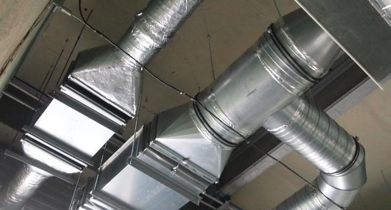
- Washer - its body has a relatively large electrical capacity due to operation in high humidity conditions.
- microwave - The main working element of the furnace is the magnetron. It has a lot of power. If the ground contact in the outlet is poor, an increase in the level of magnetic radiation may occur. Many microwave oven manufacturers equip a grounding terminal on the back of the oven.
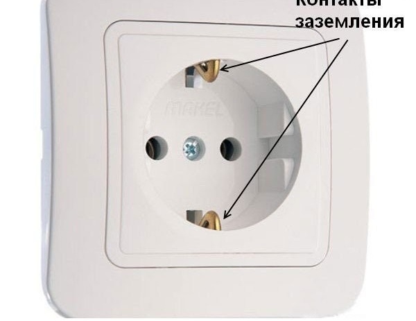
For the contact of the grounding conductor in the network and the electrical appliance, modern sockets are equipped with grounding contacts.
Grounding in household power
To provide grounding, there are six grounding systems. In some building structures, in particular, residential buildings, two main grounding systems are used.
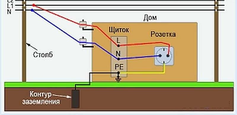
TN-S-C system - Recommended for implementation in recent years. Such a scheme with a grounded neutral at the substation is performed. Equipment in this case has direct contact with the ground. To the same consumer, earth (PE) and neutral / zero (N) are driven by one conductor (PEN). At the entrance to the electricity network of a private house, such a conductor is divided into two independent conductors.
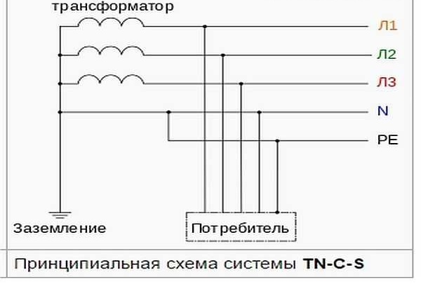
Such a system does not provide for the mandatory installation of a residual current device (RCD). Protection is provided by circuit breakers.
The disadvantage of this system is that if the PEN conductor is damaged or burned out during the substation / house section, phase voltage appears on the grounding bus of the house. This voltage does not turn off. Based on this, the PUE regulates stringent requirements for such a line: the PEN conductor must be provided with mechanical protection, and periodic local grounding on the supports of the power line must be equipped with the same.
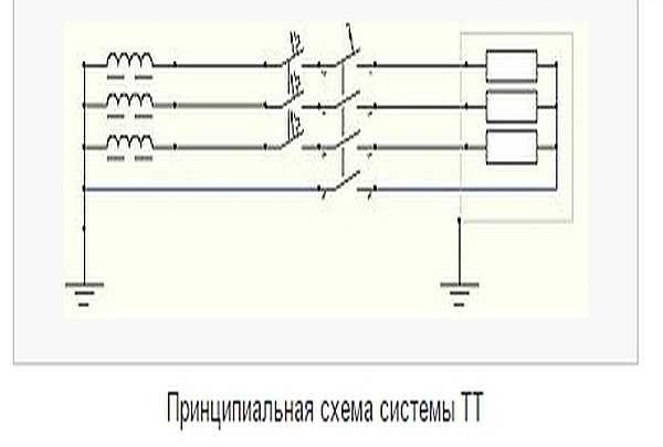
Many power lines, especially in rural areas, do not satisfy the above conditions. For such a case, another grounding system is recommended - the TT system.
Circuit diagram
Such a grounding system is implemented due to a separate wire from the grounding loop to the input shield of the building, and not from the transformer substation. This system is more resistant to damage to the protective conductor, but requires the installation of an RCD. Without equipping the system with such devices, there is no protection against electric shock.In this regard, the PUE recommends such a system only as an addition to the TN-S-C system. (If the line does not meet the requirements of the TN-S-C system).
General form
Grounding difference for 220V and 380V network
Differences in the grounding systems of private houses at an operating voltage of 220 V or 380 V are not significant. In both cases, a ground loop is constructed. The difference lies in the way the circuit is connected to the home electrical network.
In the 220V network, the voltage is single-phase. In this case, use a three-wire conductor and sockets with three contacts (phase, zero, ground electrode).
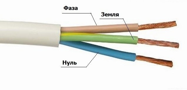
For 220 V network
In the network 380 V - three-phase voltage. In this case, a five-wire conductor and sockets with five contacts are used (phase - 3 pcs, zero, ground electrode).
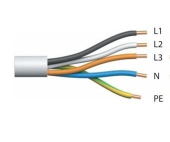
For a network of 380 V
Views
The main purpose of the grounding conductor is direct electrical contact with earth. The grounding device (ground loop) includes a ground electrode and the totality of all conductors connected to it. Including elements of their compounds.
Earthing switches are of two types:
- natural - metal structures located at a sufficient depth in the ground or reinforced concrete foundation of the building;
- artificial - a direct-use metal structure independently installed in the ground;
Artificial ground electrodes are distinguished by their design features.
- horizontal earthing switch. It is made of strip (at least 4 mm thick) or round steel and laid in soil parallel to the surface of the earth.

Ground loop
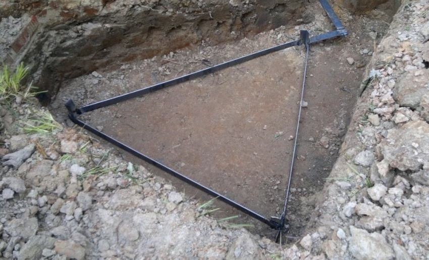
- a vertical ground electrode system is a more preferable option. Such a circuit takes up less space, but provides for a more time-consuming installation process. It is made of steel pins (a corner with a shelf of 50 - 70 mm and a thickness of at least 4 mm). The pins are interconnected by a metal strip (strip thickness of at least 4 mm).
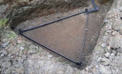
Triangle earthing switch
- combined earthing switch - includes the design features of the two previous earthing switches.
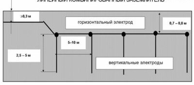
Wiring diagram
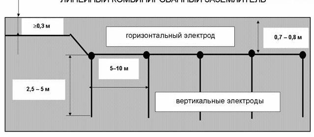
The combined installation scheme of the grounding device (circuit) is the most effective. When performing installation in compliance with the necessary rules, such a circuit will be reliable and durable.
How to make a ground loop for a private house with your own hands
The most popular protective circuit device today is the triangle circuit. It is made by connecting a metal strip of three pins buried in the ground. Such a scheme is characterized by increased reliability. If the steel connecting strip is broken or damaged on one side, the circuit will continue to function due to contact on the other side.
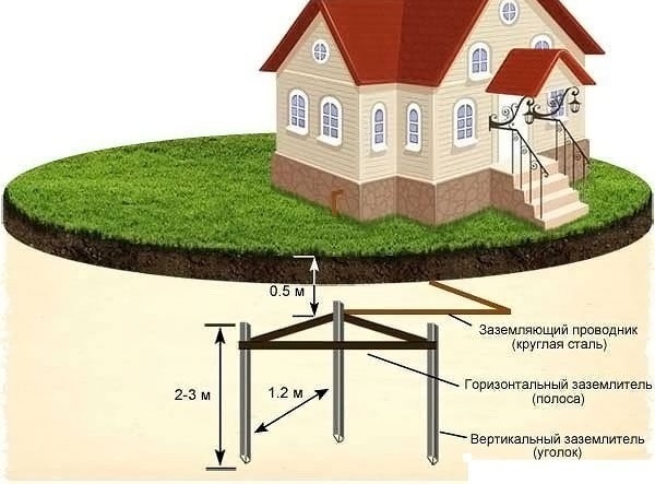
Triangle Pattern
For the manufacture and installation of the ground loop, you will need the following materials and tools:
Materials:
- steel angle 50–70mm, h = 4mm, 3 pcs. the length of one corner is not less than 2 meters;
- steel strip 50–70 mm, h = 4 mm, 4 m. for connecting pins from the corner;
- steel strip 30 mm, h = 4 mm. for the electrical connection of the ground loop and the input shield of the building. The length depends on local conditions;
- 3mm electrodes.
Tool:
- shovel, scrap, earth moving drill for arranging holes in the ground;
- grinder for cutting metal workpieces;
- bench tools (hammer, sledgehammer, file, screwdriver, clamp) for processing and assembling workpieces;
- welding machine;
- measuring tool (tape measure, square) for marking blanks;
The joints of the workpieces of the grounding loop should be made exclusively by welding. This is regulated by the requirements of the PUE. This type of connection provides the most effective electrical contact and is most resistant to corrosion.
Work with a power tool should be carried out using the necessary protective equipment: glasses, protective clothing. Work safety comes first.
When working on the preparation of a corner, it is better to cut one end face at an acute angle.Such a corner will be easier to hammer into the ground.
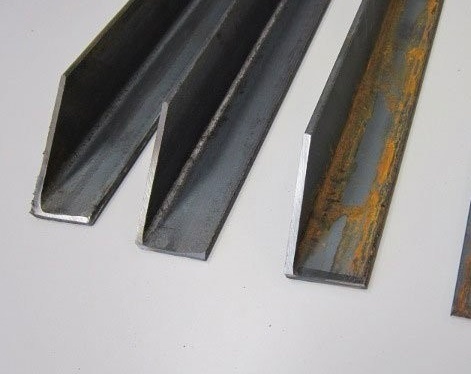
Grounding pins
Consider the process of installing the ground loop in stages.
- Procurement of metal pins and strips, according to the required dimensions.

Prepared ends for driving into the ground
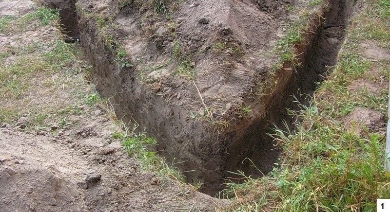
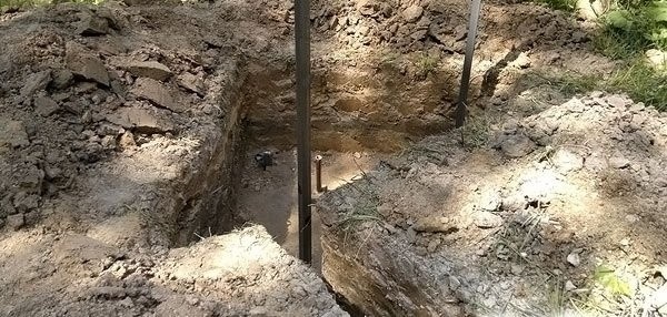
- Preparing the pit for the metal structure of the ground loop. Depth is not less than 0.5 meters.

Prepared hole
- Driving pins into the ground. Drive the pins to a depth of at least 3 meters. To connect them with a strip, it is enough to leave 200 - 250 mm.

Grounding installation
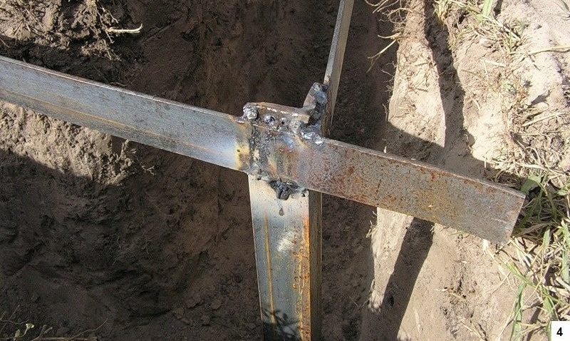
- The connection of the grounding pins with a steel strip by welding.
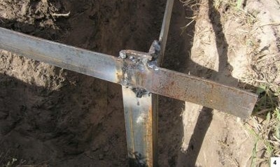
Welding method
- The final stage. The conclusion of the metal strip to the building. Arrangement of the place of electrical connection with the electrical network of the building.

Strip of steel brought to the building


This completes the installation of the ground loop. The following is the process of connecting it to the power supply network of a private house.
After connecting the circuit to the PE conductor of the electrical network, a circuit health test should be performed. For this, special electrical measuring devices are used. Such equipment is quite expensive. Therefore, a more simplified version of the circuit health check is used.
This method is carried out by connecting an incandescent lamp (100 W) to the network as follows: the phase wire is placed on the phase contact of the outlet, and the neutral wire is directly on the circuit design. In this case, you need to pay attention to the intensity of the lamp. Bright light indicates the correct operation of the circuit. Dim, about poor-quality contact at the junction of the metal elements of the circuit. In this case, the joints should be reinforced with an additional weld.
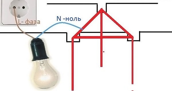
Using an incandescent lamp
When determining the value of the protective grounding resistance of the circuit with a special device, remember that the grounding value should not exceed 4 Ohms. If its value is greater, then this may indicate poor contact of the circuit with the ground. To fix this problem, you can fill the ground with water at the pin-clogging site. Due to this, the soil is compacted and the contact area will increase.
Grounding device calculation
The grounding device is also calculated from the condition of the maximum resistance value of the protective ground loop. Which should not exceed 4 ohms. The best option would be the value of the resistance of the artificial ground electrode, not exceeding a value of 1 Ohm.
To perform a thorough calculation of the ground electrode system at home, without the availability of special knowledge and technical literature is almost impossible. Since it provides for the experimental determination of soil resistivity, taking into account correction factors taking into account the drying and freezing of the soil. Determination of the spreading resistance. An element-by-element calculation of the resistance of a contour based on its geometrical dimensions, depth of soil and soil moisture. The utilization rate of vertical earthing. The presence of natural grounding. And other.
It is better that specialized organizations issuing a protocol on the suitability of the grounding loop and on the compliance of its characteristics with regulatory documents do this.
There is a simplified method.
Simplified grounding design:
For a vertical ground electrode (single), use the following formula:
R1 = 0.84 * p / L Where:
R1 - grounding resistance, Ohm;
p - soil resistivity, Ohm * m;
L is the length (depth) of the ground electrode;
For several vertical grounding pins (electrodes):
R = R1 / 0.9 * n Where:
R is the resistance of one electrode, Ohm;
n is the number of electrodes in the ground loop;
Thus, if the soil resistivity (p) is known, then the resistance of one electrode (R1) is calculated according to the first formula.The obtained value is substituted into the second formula and the number of electrodes (n) is determined, with the set length (L).
In the case when the specific soil spacing is not known, you can use the look-up table:
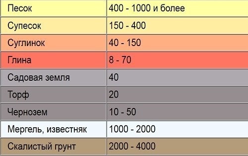
Values for common soils
If in practice it was not possible to find or measure the value of the soil resistivity in the area for mounting the circuit, use the test immersion method of the electrode. The method consists in periodically measuring the resistance of the electrode as it immerses in the ground. You can stop clogging the electrode when the resistance indicators have stopped declining. This means that the electrode has reached a depth at which the soil resistivity becomes constant. In the future, this electrode must be connected with a metal strip with other elements of the circuit.
Choosing a place for installation
Effective and safe operation largely depends on the correctly selected location for the arrangement of the circuit. There are several recommendations on this subject:
- Do not place the ground loop in a place where people or animals are constantly or frequently. At the time of the breakdown of insulation and the removal of voltage into the soil, a person or animal in the immediate vicinity may be affected. It is better to take measures to fence such a site.
- Some experts recommend placing the outline on the north side of the building. This is due to wetter moist in such a plot.
- If the soil is too moist and there is a high probability of corrosion of the contour metal, then it is better to make it from steel of large cross section. And also the circuit design can be coated with special conductive materials that will protect against corrosion, but will not worsen electrical contact with the ground.
- Do not place the ground loop close to heat communications. Overdried negatino soil affects the resistance of the circuit.
- It is forbidden to locate the circuit in the immediate vicinity with a gas pipeline passing in the ground.
- The depth of the contour should be below the freezing level of the soil, but not less than 0.5 m.
If you follow these recommendations, you can be sure of the correctness of the selected place, and the reliable operation of the ground electrode.
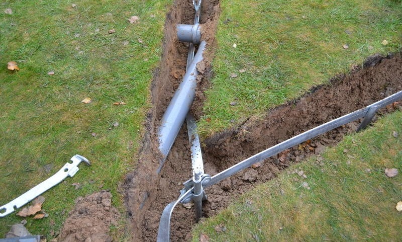
Earthworks and assembly
Earthwork must be done carefully. Previously, you should consider the perimeter of the work, taking into account the possible occurrence in the ground of communications for various purposes: pipelines, telephone lines, cable power lines. It is better to position the path away from such objects.
Earthwork is carried out using standard tools: shovels, scrap, drill.
Ground loop installation
When arranging trenches, they must be made wide enough. This is necessary for the convenience of welding. Indeed, the effectiveness of the protective earthing system depends on the quality of the welding joints.
The bolted connection is allowed to be used only at the place of output of the steel strip directly to the house and its connection with the input shield of the mains.
In some factory-made grounding conductors, bolted connections are used, but high-quality contact in these cases is achieved due to pressure plates and copper-plated electrode surfaces.
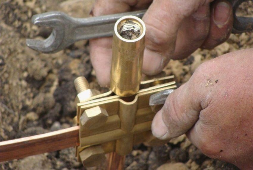
Connection of copper-plated contour elements with pressure plates
Welding joints must be continuous, the length of the weld is at least 100 mm.
For clarity, a video is presented in which the process of arranging a protective ground loop in a private house is presented.
The video was taken from the Youtube online resource, is used for educational purposes and is not an advertisement.
Video: self-installation of the ground loop
Definitely, a protective earthing system in a private house is a necessity. As you can see, the implementation of such a task is quite feasible for everyone.The main thing is to choose the right installation location for the circuit, correctly calculate its parameters and select the appropriate materials. A well-made grounding will protect your home and those living in it.