How to make a wind generator with your own hands: an overview of the assembly technology of 2 different designs
Electricity is steadily rising in price. To feel comfortable outside the city in hot summer weather and a frosty winter day, you must either thoroughly spend money, or go in search of alternative energy sources. Russia is a vast country with large flat territories. Although slow winds prevail in most regions of our country, sparsely populated areas are blown by powerful and violent air currents. Therefore, the presence of a wind generator in the economy of the owner of suburban real estate is often justified. A suitable model is selected based on the area of application and the actual purpose of use.
Content
Windmill # 1 - rotor type design
You can make a simple rotor-type windmill with your own hands. Of course, he is unlikely to be able to supply electricity to a large cottage, but to provide a modest garden house with electricity is quite within his power. With its help it is possible to provide light in the evening with outbuildings, illuminate garden paths and the adjoining territory.
More information about other types of alternative energy sources can be found in this article:https://aquatech.tomathouse.com/en/otoplenie/alt_otoplenie/alternativnye-istochniki-energii.html

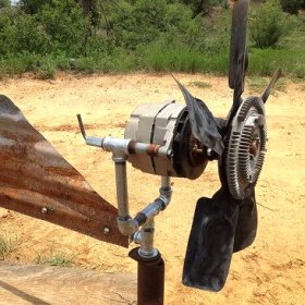
So or almost so does a do-it-yourself rotary wind generator. As you can see, there is nothing super complicated in the design of this equipment
Preparation of parts and consumables
To assemble a wind generator, the power of which will not exceed 1.5 kW, we need:
- generator from the car 12 V;
- 12 V acid or helium battery;
- converter 12V - 220V to 700 W - 1500 W;
- a large capacity of aluminum or stainless steel: a bucket or a voluminous pan;
- car battery charging relay and charge warning lamp;
- semi-hermetic button-type switch for 12 V;
- a voltmeter from any unnecessary measuring device, you can use a car;
- bolts with washers and nuts;
- wire cross section 2.5 mm2 and 4 mm2;
- two clamps with which the generator will be attached to the mast.
To do the work, we will need metal scissors or a grinder, tape measure, marker or construction pencil, screwdriver, keys, drill, drill, nippers.
Most owners of private homes do not recognize the use of geothermal heating, however, such a system has prospects. More information about the advantages and disadvantages of this complex can be found in the following material:https://aquatech.tomathouse.com/en/otoplenie/alt_otoplenie/geotermalnoe-otoplenie-doma-svoimi-rukami.html
Design progress
We are going to make a rotor and remake a generator pulley. To get started, we need a cylindrical metal tank. Most often, a pan or bucket is fitted for these purposes. Take a tape measure and a marker or a construction pencil and divide the capacity into four equal parts. If we cut metal with scissors, then to insert them, you must first make holes. You can also use a grinder if the bucket is not made of painted tin or galvanized steel. In these cases, the metal will inevitably overheat. We cut the blades without cutting them to the end.

In order not to be mistaken with the dimensions of the blades that we cut through in the tank, it is necessary to make careful measurements and carefully recount everything
In the bottom and in the pulley we mark and drill holes for the bolts. At this stage, it is important not to rush and to arrange the holes in compliance with symmetry, so that during rotation to avoid imbalance. The blades should be bent, but not too much. When performing this part of the work, we take into account the direction of rotation of the generator. Usually it spins clockwise. Depending on the angle of bending, the area of influence of wind flows increases, and, hence, the speed of rotation.

This is another version of the blades. In this case, each part exists separately, and not as part of the container from which it was cut

Since each of the blades of the windmill exists separately, you need to screw each one. The advantage of this design is its increased maintainability
The bucket with the finished blades should be mounted on the pulley using bolts. Using the clamps, install a generator on the mast, then connect the wires and assemble the circuit. It is better to rewrite the circuit, color of wires and marking of contacts in advance. The wires also need to be fixed on the mast.
To connect the battery, use 4 mm wires2whose length should not be more than 1 meter. We connect the load (electrical appliances and lighting) using wires with a cross section of 2.5 mm2. Do not forget to put the converter (inverter). It is connected to the contacts 7.8 with a wire of 4 mm2.

The design of the wind turbine consists of a resistor (1), a generator starter winding (2), a generator rotor (3), a voltage regulator (4), a reverse current relay (5), an ammeter (6), a battery (7), a fuse (8) circuit breaker (9)
Advantages and disadvantages of such a model
If everything is done correctly, this wind generator will work without creating problems for you. With a 75A battery and with a 1000 W converter, it can power street lighting, burglar alarm, video surveillance devices, etc.

The operation diagram of the installation clearly demonstrates how exactly wind energy is converted into electricity and how it is used for its intended purpose
The advantages of this model are obvious: it is a very economical product, can be easily repaired, does not require special conditions for its functioning, it works reliably and does not violate your acoustic comfort. The disadvantages include low productivity and a significant dependence on strong gusts of wind: the blades can be disrupted by air currents.
It is possible to make a solar battery yourself. Step-by-step instructions are located here:https://aquatech.tomathouse.com/en/otoplenie/alt_otoplenie/solnechnaya-batareya-svoimi-rukami.html
Windmill # 2 - axial magnet design
Until recently, axial windmills with ironless stators on neodymium magnets were not made due to the inaccessibility of the latter. But now they are in our country, and they cost less than initially. Therefore, our craftsmen began to produce wind generators of this type.

Over time, when the capabilities of a rotary wind generator will no longer provide all the needs of the economy, it is possible to make an axial model with neodymium magnets
What needs to be prepared?
As the basis of the axial generator, you need to take the hub from a car with brake discs. If this part was in operation, it must be disassembled, bearings should be checked and lubricated, and the rust cleaned. The finished generator will be painted.

To qualitatively clean the hub from rust, use a metal brush that can be mounted on an electric drill. The hub will look great again
Magnet distribution and fixing
We have to stick magnets on the rotor discs. In this case, 20 magnets 25x8mm in size are used. If you decide to make a different number of poles, then use the rule: in a single-phase generator there should be how many poles, so many magnets, and in a three-phase generator it is necessary to observe the ratio of 4/3 or 2/3 of the pole to the coils. Magnets should be placed alternating between the poles. For their location to be correct, use a template with sectors printed on paper or on the disc itself.
If there is such a possibility, it is better to use rectangular magnets rather than round magnets, because for rounds the magnetic field is concentrated in the center, and for rectangular ones along their length. Opposing magnets must have different poles. In order not to mix anything up, apply a “+” or “-” on their surface with a marker. To determine the pole, take one magnet and bring others to it. On plus surfaces, put plus and minus on repulsive surfaces. On the discs, the poles must alternate.

The magnets are correctly positioned. Before fixing them with epoxy, it is necessary to make plasticine boards so that the adhesive can freeze, and not glass on the table or floor
To fix the magnets, you need to use a strong glue, after which the bonding strength is additionally strengthened with epoxy. It is filled with magnets. To prevent resin from spreading, you can make plasticine borders or simply wrap tape with tape.
Three-phase and single-phase generators
A single-phase stator is worse than a three-phase one, because it gives vibration when loaded. This is due to the difference in the amplitude of the current, which occurs due to its non-constant return for a moment in time. The three-phase model does not suffer from this drawback. The power in it is always constant, because the phases compensate each other: if the current drops in one, and it grows in the other.

In the dispute of single-phase and three-phase variants, the latter comes out victorious, because additional vibration does not extend the service life of the equipment and irritates hearing
As a result, the return on a three-phase model is 50% higher than the same single-phase rate. Another advantage of the absence of unnecessary vibration is acoustic comfort when working under load: the generator does not buzz during its operation. In addition, vibration always destroys the wind generator before the end of its life.
Coil Winding Process
Any specialist will tell you that a careful calculation must be made before winding coils. And any practitioner will do everything intuitively. Our generator will not be too fast. We need the 12-volt battery charging process to start at 100-150 rpm. With such initial data, the total number of turns in all coils should be 1000-1200 pieces. It remains to divide this figure by the number of coils and find out how many turns will be in each.
To make a wind generator at low speeds more powerful, you need to increase the number of poles. In this case, the frequency of the current oscillation will increase in the coils. For winding coils it is better to use a thick wire. This will reduce the resistance, and, therefore, the current strength will increase. It should be noted that at high voltage the current may turn out to be “eaten up” by the resistance of the winding. A simple home-made machine will help you quickly and accurately reel high-quality coils.

The stator is marked, the coils are laid in place.For their fixation, an epoxy resin is used, runoff of which is again opposed by plasticine boards
Due to the number and thickness of the magnets located on the disks, the generators can vary significantly in their operating parameters. To find out what power to expect as a result, you can wind one coil and scroll it in the generator. To determine the future power, you should measure the voltage at certain revolutions without load.
For example, at 200 rpm it turns out 30 volts with a resistance of 3 ohms. Subtract the battery voltage of 12 volts from 30 volts, and divide the resulting 18 volts by 3 ohms. The result is 6 amperes. This is the amount that goes to the battery. Although practically, of course, it comes out less due to losses on the diode bridge and in the wires.
Most often, the coils are made round, but it is better to stretch them a little. At the same time, more copper is obtained in the sector, and coil turns are straighter. The diameter of the inner hole of the coil should correspond to the size of the magnet or be slightly larger than it.

Preliminary tests of the resulting equipment are carried out, which confirm its excellent performance. Over time, this model can be improved.
When making a stator, keep in mind that its thickness should correspond to the thickness of the magnets. If the number of turns in the coils is increased and the stator is thicker, the inter-disk space will increase, and the magnetic flux will decrease. As a result, the same voltage can be generated, but less current due to the increased resistance of the coils.
Plywood is used as a form for the stator, but it is possible to mark sectors for coils on paper and make borders from plasticine. The strength of the product will increase fiberglass placed on the bottom of the mold and on top of the coils. Epoxy must not adhere to the mold. To do this, it is lubricated with wax or petroleum jelly. For the same purposes, you can use a film or tape. The coils are fixed together, the ends of the phases are brought out. Then all six wires are connected by a triangle or a star.
The generator assembly is tested using hand rotation. The resulting voltage is 40 volts, and the current strength is approximately 10 amperes.
Final stage - mast and screw
The actual height of the finished mast was 6 meters, but it would be better to make it 10-12 meters. The base for it needs concreting. It is necessary to make such a fastening so that the pipe can be raised and lowered using a manual winch. A screw is attached to the top of the pipe.

PVC pipe - a reliable and fairly lightweight material, using which you can make a wind turbine screw with a predetermined bend
To make a screw, you need a PVC pipe with a diameter of 160 mm. A six-blade two-meter screw is to be cut from it. It makes sense to experiment with the shape of the blades in order to increase the torque at low revs. The propeller must be removed from strong winds. This function is performed using a folding tail. The generated energy is stored in batteries.

The mast must be raised and lowered using a hand winch. Additional structural stability can be imparted using tension cables
Your attention is given two options for wind generators, which are most often used by summer residents and owners of suburban real estate. Each of them is effective in its own way. Especially the result of the use of such equipment is manifested in areas with strong winds. In any case, such an assistant in the household never hurts.

3 comments