How to connect a single-key switch: a simple instruction for dummies and not so
Connecting a single-button light switch is a task that sometimes confronts a home electrician. Most lighting fixtures are controlled by just such switches. This article describes in detail the sequence of actions for connecting a single-key switch and installing it at home without assistance.
Content
Preparatory work before installing the switch
Preliminary preparatory steps must be taken to connect the lighting switch. Installation is carried out from the nearest junction box to which power is supplied - network cables for supplying electric current.
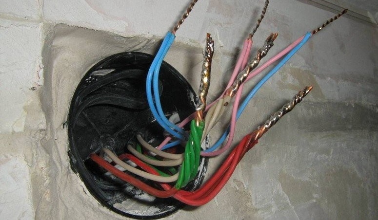
Power to the switch and fixtures is supplied from the junction box
Three lines are laid — one from the junction box to the luminaire, the other from it to the switch. The third comes from the shield. As a rule, two- or three-core wires of an installation type are used, that is, with a copper (or aluminum) core made of solid metal. In everyday life, such a wire is called rigid, in contrast to soft, in which under the insulation there are pigtails made of small hairy conductors. On the marking, the rigid cable is indicated by the letter “U”. The conductor cross-sectional area is selected in accordance with the load. For a conventional lamp or chandelier, in which up to 3 lamps are combined, a wire with a cross-sectional area of 1.5 mm is enough2.
If energy-saving or LED bulbs are used, the cross-section of the conductor can be reduced to 0.75 mm in order to save2.
The type of wiring installation can be of two types - internal (hidden) and external. Hidden wiring is installed in the thickness of the wall or ceiling. The outer one passes along their surface, the cable is packed in a corrugation or cable channel, which are mounted on the wall with special brackets or other fixing material.
After the wires are separated, you can proceed to install the switch.
Single-key switch wiring diagram
The principle of operation of the switch is based on breaking the power circuit of the bulb or any other device. Switching the toggle switch activates a contact pair, which disconnects the power wire from the current consumer.
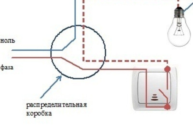
The switch usually opens the phase wire.
When assembling the circuit, you should pay attention to the reliability of the contacts. If the wires have large gaps, then at one point a so-called electric arc can arise, the temperature of which is sufficient to melt and ignite the insulation. This can lead to smoke in the living room and even a fire. In order to avoid such phenomena, the following connection methods are used:
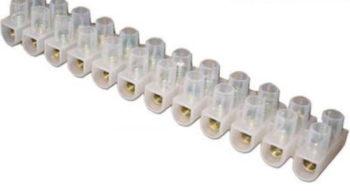
- electrical terminal blocks. Connection with terminal blocks is especially recommended in cases where it is necessary to connect wires with conductors of different materials, for example, aluminum and copper;
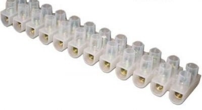
When connected via a terminal strip, a reliable and reliable contact is ensured, so that the wires will never spark
- twisting. Made with pliers. Having removed the insulation by 1.5–2 cm with a knife, the wires are twisted into a tight connection. After that, they are soldered with tin and insulated with electrical tape (not with adhesive tape!). In the case of connecting one lamp, such connections will be 3. If the home network is equipped with grounding and a three-core cable is used, all the "earth" wires are connected into one node inside the junction box.

The wires are tightly twisted with pliers and then soldered
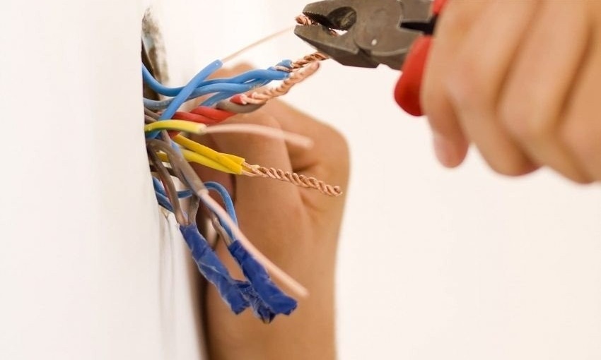
Twisting of copper and aluminum wires is also possible. But if the connection is overloaded, aluminum can melt, as it has a lower melting point than copper. Contact will be interrupted.
Tools and materials for connecting
To connect, you will need the following tools:
- Knife.
- Electrical screwdriver.
- Household voltage indicator.
- Pliers.
From materials at hand should be:
- Wires of the required length.
- Junction box.
- Terminal blocks or electrical tape.
- Cartridge for the lamp (and the lamp itself).
- One-key switch.
Pay attention to our article, which describes in detail how to choose the right switches:https://aquatech.tomathouse.com/en/ehlektrosnabzhenie/rozetki-i-vyiklyuchateli-vidyi.html.
Photo gallery: materials for mounting the circuit breaker
-

- Cable length is pre-measured by tape measure at the work site

-
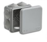
- Depending on the type of wiring, external or built-in (internal) junction boxes must be used.

-

- The cartridge is attached to the ceiling with self-tapping screws

-

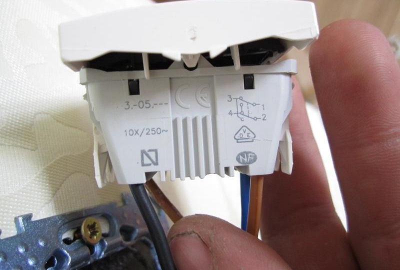
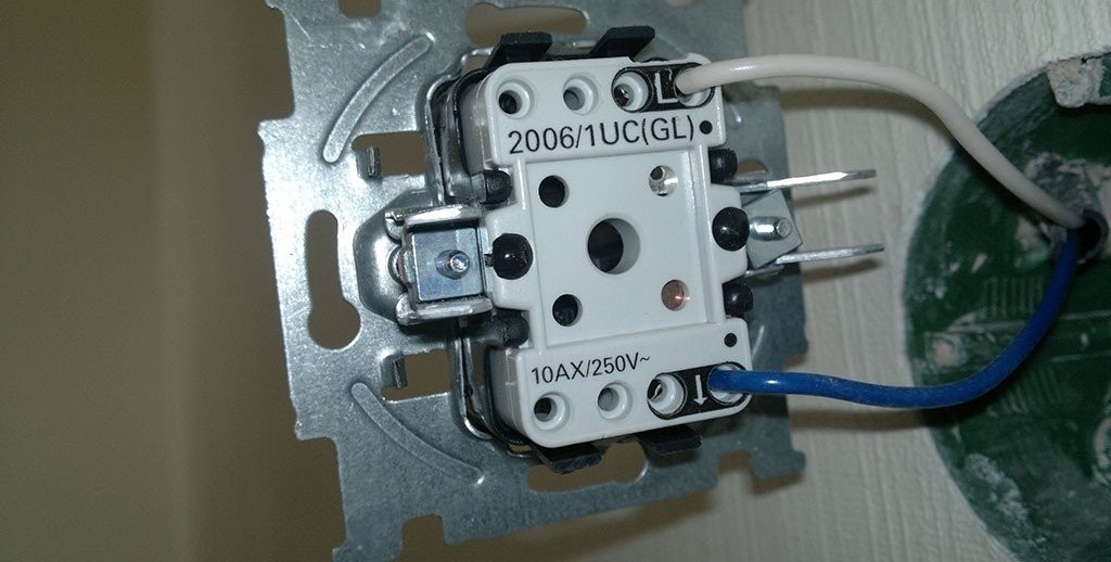
- The base of the “right” switch can be ceramic or made of high-quality plastic

Step-by-step instructions for connecting a single-key switch
If all the tools and materials are ready, you can start assembling. Conditionally, the procedure can be divided into two steps:
- connection of switch contacts and bulbs;
- cable switching inside the junction box.
Before this, all wires are fixed at the places allocated to them in the cable channels or corrugation. The junction box and socket box for the switch are firmly installed in (or on) the wall. The procedure does not matter much, but experienced electricians always start connecting from the periphery - the switch and the bulb, and end up connecting the wires in the box.
Switch and lamp connection
- If the lamp is already connected, you can start with the switch. If not, connecting two wires to it will not be difficult. There are two connectors in the cartridge, each of them needs to be inserted with one of the cable cores and fixed with a clamping screw.
Two wires are supplied to the cartridge and screwed to the corresponding contacts
- After that it connects switch. To do this, you need to disassemble it - disconnect the key mounted on the plastic latches, and get the ceramic (or plastic) base.
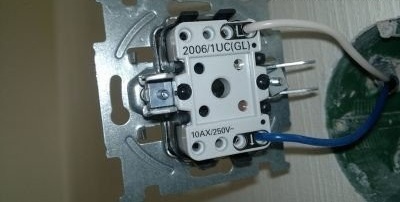
When connecting the wires to the switch and the cartridge, the order of connecting the wires does not matter

There are various models of switches, but in the bulk they are mounted in the socket box using a spacer mechanism mounted on the base. Before fixing the base, you need to connect the wires to it.To do this, the clamp screws are loosened, the wires are inserted into the sockets, and the screws are clamped again. It is important not to overtighten the threaded fastener - it must be tightened so as not to damage the screw splines.
If there is no socket and the switch is mounted externally, the base is screwed onto the wall surface with two screws.
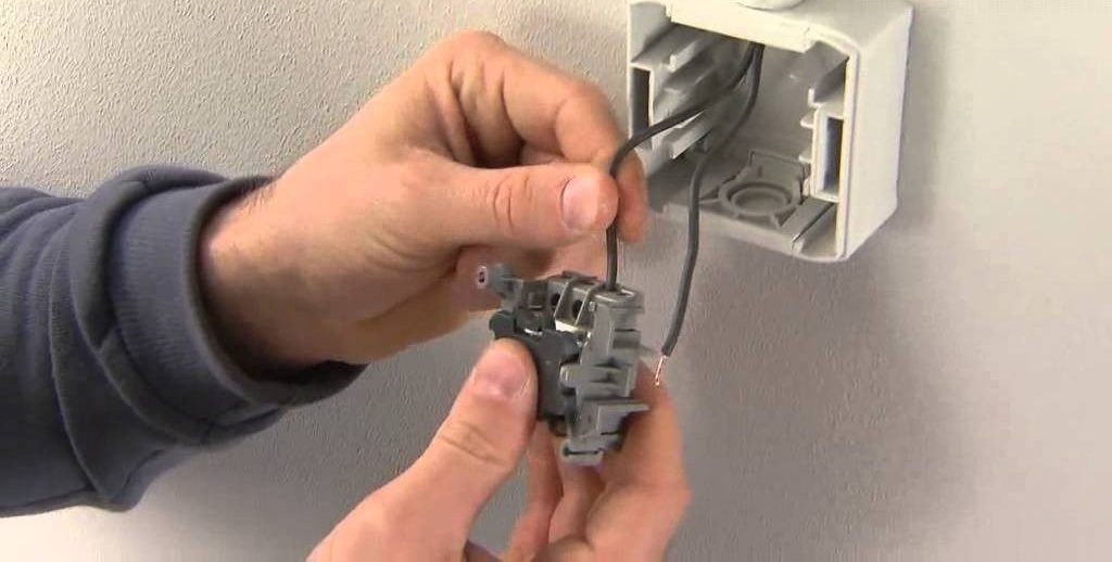
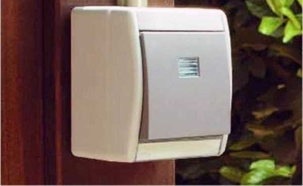
The external switch is mounted directly on the wall surface.
At this stage, it must be positioned correctly. It is customary to set the switch so that it is turned off by pressing the button down, and turning it on is up. This is done for security reasons. If suddenly something accidentally falls on the switch from above, the mechanism will work to break the circuit and trip.
After screwing the screws into the wall and fixing the base, the installation of the switch can be considered complete. All that remains is to insert the key into place, but this can be done at the very end, after checking the operation of the entire circuit.
Switching cables in the junction box
Before starting the connection of the conductors, it is necessary to disconnect the line supplying electric current to the junction box. To do this, turn off the plugs or circuit breaker on the meter board.
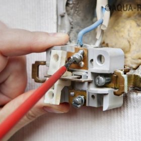
It is very convenient to carry out switching according to the color of the cores. Using the voltage indicator, you need to determine which of the cores is in phase, and in which is zero. Touching the phase wire will cause the diode to glow on the probe.

The indicator is activated by applying a finger to the red cap
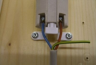
Usually the “phase” is connected to the red core of the wire, “zero” to the blue, and “grounding” to the white.
- The phase core is connected to one of the wires leading to the switch. This is necessary so that the “phase” is interrupted when the lamp is turned off, since it is it that carries the risk of electric shock.
- The second core, coming from the switch, is connected to the red wire from the lamp. And the blue wire from the lamp is connected to the blue power wire coming from the electrical panel. Thus, the circuit closes. Before testing the connection, the switch is put into the “Off” position, that is, press the down key. After that, plugs (or machines) on the flap are turned on and the switch button is pressed. If everything works, you need to turn off the circuit again and wind up the bare connections with electrical tape. Carefully lay the wires inside the box and close it with the lid.
- The key on the switch is installed. Assembly and connection completed.

If everything works fine, you can assemble the switch and close the junction box
If the wiring in the house is made with three-core cables, all the white conductors of the "earth" are interconnected.
Video: single-key switch wiring diagram
You may also be interested in material with instructions for connecting a passage switch:https://aquatech.tomathouse.com/en/ehlektrosnabzhenie/kak-sdelat-prohodnoy-vyiklyuchatel.html.
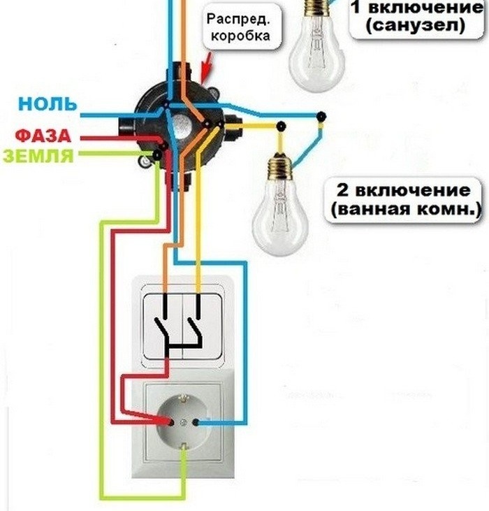
How to connect 3 sockets and 1 switch from one junction box
Sometimes you need to connect one or more sockets to an existing wiring. This can easily be done by inserting another cable into the junction box.
It should be noted that for outlets it is customary to use connecting wires with a larger cross-sectional area. This is due to the fact that a variety of household appliances are included in the outlet. It can be a kettle or, for example, a vacuum cleaner. Their power consumption is higher than that of a simple light bulb, and therefore thin wires can heat up, which is undesirable. Therefore, sockets are connected with cables, the cross section of which starts from 2.5 mm2.
The connection process consists in connecting the wire to the power line that came to the junction box from the switchboard. As with the installation of the circuit breaker, all work should be carried out only with the plugs turned off.
- As in the first case, the sockets are first mounted on the wall. Theoretically, you can install any number of outlets, connecting them together in parallel.

To connect outlets with each other, special jumpers are used
- Then a cable is laid from them to the junction box. The lid is removed and the conductor starts inside.
- Two cores are connected to the trunk line that came from the shield. If everything is done correctly, the indicator will show the presence of voltage in the outlets (the red LED will light up).
- After that, all the wires are again laid inside the box and closed with a lid.
The line of sockets is connected directly to the phase and neutral wires coming from the shield
When connecting wires using twists, it is advisable to carefully strip all contacts with a knife or a small file. Sometimes the old wiring is oxidized at the junction and contact from this becomes unstable. When adding new wires, twisting is done using pliers.
In order to avoid a short circuit, the insulation must completely exclude possible contacts of wires with different poles.
Video: Connecting a single-key switch and outlet
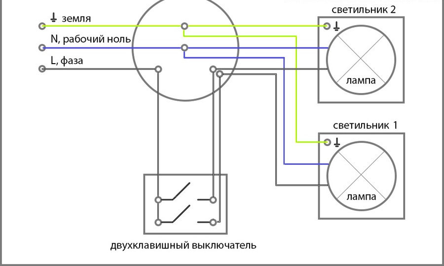
How to connect a single-key switch to two bulbs
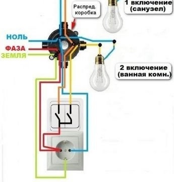
If two bulbs located in different places must be turned on simultaneously from one switch, the same connection scheme is used.
The supply of current to the lamps is controlled by one switch, but the connection options for the lamps themselves may vary.
New cable in box
Another cable is put into the junction box. The ends of the wires are cleaned and connected to the same terminals as the first lamp. This will take some extra volume inside the box, but if there is enough space, then nothing bad will happen.
One way to connect two light bulbs to one switch is to connect both pairs of wires to the same pins.
Cable from an existing device
A tap is mounted from an existing lamp, which is connected to it in parallel. To do this, two additional contacts (“zero” and “phase”, red and blue) are inserted into the cartridge of the first lamp and pulled to the second lamp.
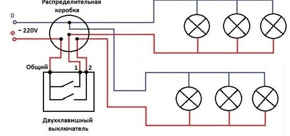
The advantage of a parallel lamp connection circuit is the ability to use them in any quantity
The choice of connection is selected depending on the situation. The second option is used more often, since often in the junction box there is not enough space for the input of additional cables. In addition, in this way you can connect not only two lamps, but also a larger number of them. The main thing is to observe the principle of parallel connection of wires.
Do you want the lamps to turn on smoothly? See the connection diagrams of such a system in our next article:https://aquatech.tomathouse.com/en/ehlektrosnabzhenie/plavnoe-vklyuchenie-lamp-nakalivaniya-220.html.
When installing home electrical equipment, you need to remember to comply with safety standards. Before you start, you must turn off the power to the network. It is better to use dielectric-coated tools and cables with the appropriate cross-section. Do not throw bare ends of conductors onto radiators or water pipes. In addition, the regulatory parameters of the connections must be observed.