RCD purpose: connection scheme in a household electrical network, installation

Modern methods of protecting a person from electric shock in a household electrical network include the installation of an RCD. The correctness of its operation and the reliability of protection depends on a correctly selected device and the quality of installation.
Content
What is the need for an RCD?
To understand the principle of operation of the RCD and the features of its installation, a number of key points should be considered.
First of all, you need to understand that the use of a large number of electrical appliances in everyday life leads to an increased risk of a person falling under the influence of electricity. Therefore, the formation of protective nodes that protect against this dangerous factor is a necessity in modern residential premises. The protective shutdown device itself is an element of the protection system, and functionally has several purposes:
- In the event of a short circuit in the wiring, the RCD protects the room from fire.
- When a human body is exposed to an electric current, an RCD cuts off the power in the entire network or a specific electrical appliance to protect it (local or general shutdown depends on the position of the RCD in the power supply system).
- And also the RCD disconnects the supply circuit when there is an increase in the current in this circuit by a certain amount, which is also a protection function.
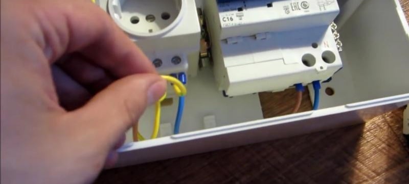
Structurally, an UZO is a device that has a protective shutdown function, looks similar to a circuit breaker automatically, but has a different purpose and function of a test inclusion. The RCD is mounted using a standard din rail connector.
RCD design can be bipolar - a standard two-phase AC 220V electrical network.
Such a device is suitable for installation in standard buildings (with electrical wiring made by a two-wire cable). If the apartment or house is equipped with wiring with three phases (modern new buildings, industrial and semi-industrial premises), then an RCD with four poles is used.
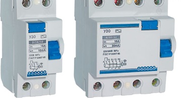
Bipolar and four-pole execution
A diagram of its connection and basic characteristics of the device are plotted on the device itself.
- Serial serial number of the device, manufacturer.
- The maximum current at which the RCD operates for a long time and performs its functions. This value is called the rated current of the device, it is measured in amperes. It usually corresponds to the standardized current values of electrical appliances. Designated on the instrument panel as In.This value is set due to the cross-section of the wire and the structural design of the contact terminals of the RCD.
-
Standardized current values (6, 16, 25, 32, 40, 63, 80, 100, 125 A).
- RCD cutoff current. The correct name is the rated breaking differential current. It is measured in milliamps. On the case of the device is marked - I∆n. The indicated value of the leakage current indicator triggers an RCD protective mechanism. The operation occurs if all other parameters do not reach emergency values and the installation is completed correctly. The leakage current parameter is determined by standard values.
-
Standardized leakage current (6, 10, 30, 100, 300, 500 mA)
- The value of the nominal differential current, which does not lead to an emergency shutdown of the RCD, operating under normal conditions. Correctly called the nominal non-tripping differential current. Designated on the housing - In0 and corresponds to half the value of the cut-off current of the RCD. This indicator covers the range of values of the leakage current, during the appearance of which an emergency operation of the device occurs. For example, for an RCD device having a cut-off current of 30 mA, the value of the non-tripping differential current will be 15 mA, and the RCD will shut down accidentally during the formation of a leakage current in the network with a value corresponding to the range from 15 to 30 mA.
- The voltage value of the operating RCD is 220 or 380 V.
- The casing also indicates the highest value of the short-circuit current, at the time of formation of which the RCD will continue to work in good condition. This parameter is called nominal conditional short circuit current, denoted as Inc. This current value has standardized values.
-
The calculated standardized value of short-circuit currents is 3000, 4500, 6000, 10 thousand A.
- Indicator of the rated device shutdown time. This indicator is designated as Tn. The time that he describes is the period from the moment of formation of the differential tripping current in the circuit to the time at which the complete extinction of the electric arc occurred on the power contacts of the RCD device.
In addition, the RCD panel displays the temperature range of the device, the numbering and purpose of the terminals, the designation of the switch (on / off).
Notation example:
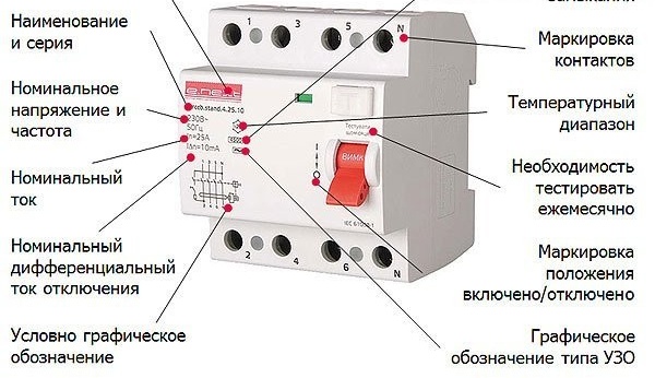
An example of the designation of the main characteristics of the device
The principle of operation of the device
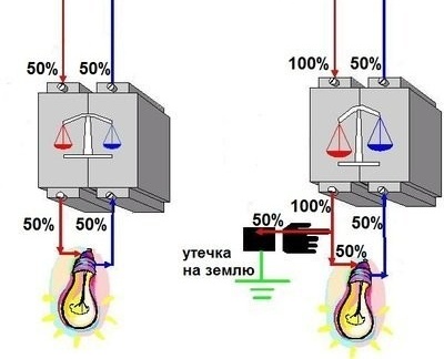
In the event of a leakage current in the room wiring, a difference in the current indicators appears on the outgoing and incoming terminals of the RCD. At this moment, the protective fuse of the device compares the value of the leakage current with the nominal allowable value and causes the device to trip if the permissible value is exceeded. There is a so-called emergency shutdown.
The disconnection time of the RCD is from 0.05 to 0.2 s. In no case should it be more than 0.3s. A longer shutdown time leads to grave consequences of the influence of electric current on the human body.
A graphic example of the operation of an RCD during the formation of a leakage current in a network. The current at the output of the RCD is larger in magnitude than the current at the input. The balance is disturbed, as a result of which the contact opens.
The principle of operation of the device
It should be remembered that the RCD responds only to the occurrence of leakage currents in the circuit section located after the RCD. If a leak occurs on the site before the RCD, it will not fulfill its function.
An example of the actions of the device in the event of a leak in the circuit coming to the RCD. In this case, the current balance at the input and output of the device is not violated, the device does not work:
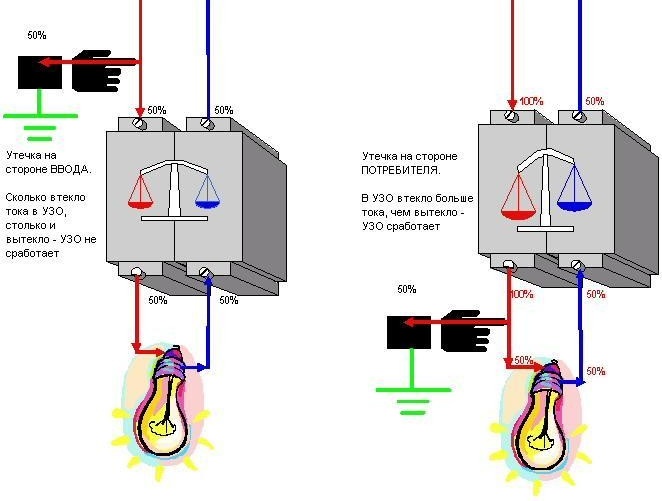
The reaction of the device to leakage in various parts of the circuit
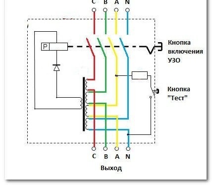
The main structural element of the RCD is made in the form of a current transformer 1. The current transformer is made on a toroidal ferromagnetic core. The current transformer has three windings. Two of these windings have a different direction.One is powered from the phase wire L3, and the other from the zero N. The third winding 2 is a control winding. Current I1 passes through the phase winding, and current I2 through the zero current (to and from electrical equipment, respectively). The coil of the control coil in normal operating mode is without induced voltage.
In normal operating mode, the current flowing in the two primary windings is directed oppositely, but the same in magnitude. At this time, two magnetic fluxes appear on the transformer core, which have the opposite direction and, therefore, are compensated. The total (full) magnetic flux at any time is equal to zero (Ф1 + Ф2 = 0).
When a person touches a live conductor, a current different in magnitude from the current flowing through the neutral conductor will flow in the phase conductor. The current balance and the balance of magnetic fields in the current transformer of the RCD are disturbed. The current flowing through the phase wire is larger, since the leakage current I is added to the rated current I1. For a transformer, this differential current is different from the rated one. If the balance of magnetic fluxes in the transformer is violated, the total magnetic flux acquires a value different from zero (F1 + Ф2 ≠ 0). According to physical laws, such a magnetic flux creates an electric current in the conductor of the control winding 2 of the UZO current transformer 1. The current, having reached the value necessary for the operation of the trip relay 2, disconnects the contact mechanism of the UZO. As a result, the electrical device located after the RCD is de-energized. And also the entire electric circuit supplying power to the consumer remains without voltage. A person who touches any part of such a circuit is saved from the action of electric current due to the operation of RCDs.
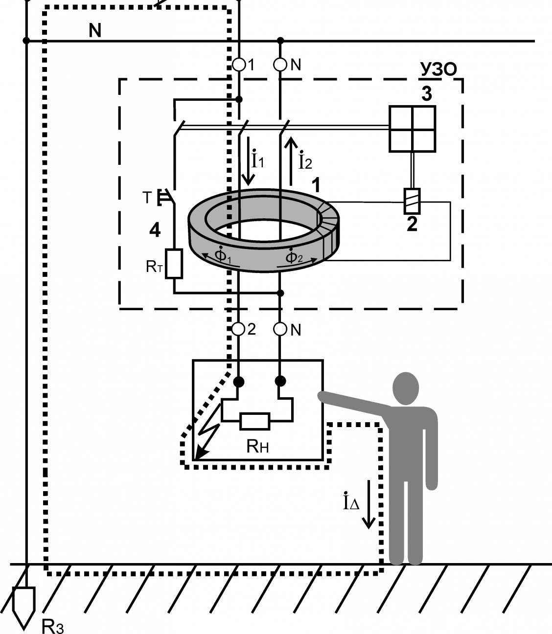
The principle of operation of the RCD
How to pick up
The first parameter by which the RCD is selected is the type of wiring in the room where the device will be installed. For rooms with two-phase wiring voltage of 220 V, an RCD with two poles is suitable. In the case of three-phase wiring (modern apartments, semi-industrial and industrial premises), a four-pole device should be installed.
To install the correct circuit of protective devices, you will need several protective devices of various sizes. The difference will be in the place of their installation and the type of circuit to be protected.
The selection of RCDs must be carried out taking into account certain electrical parameters in the home electrical network, namely:
- The cut-off current of the RCD must be greater than the largest current consumed in the room (apartment) by 25%. The magnitude of the maximum current can be found in the utility structures serving the premises (housing office, energy service).
- The rated current of the RCD, it should be chosen with a margin in relation to the rated current of the circuit breaker of the machine that protects the circuit section. For example, if the circuit breaker is designed for a current of 10 A, then the RCD should be selected with a current of 16A. It should be borne in mind that RCD protects exclusively from leakage, and not from overload and short circuit. Proceeding from this, a mandatory requirement is the installation of a circuit breaker in a circuit section together with an RCD.
- Differential current RCD. The value of the leakage current, at the time of the occurrence of which the device will perform an emergency power off. In domestic premises, in order to protect several consumers (group of sockets, group of fixtures), an RCD with a differential current setting of 30 mA is selected. Choosing a device with a lower setting is fraught with frequent false shutdowns of RCDs (current leaks are always present in the network of any room, even during the minimum load). For groups or single consumers who are in conditions of high humidity (shower, dishwasher, washing machine), an RCD should be installed with a differential current value of 10 mA. Operating conditions in a damp environment are considered to be particularly hazardous from the point of view of electrical safety. You do not need to install a single RCD on many consumer groups. For small rooms, it is permissible to install one RCD with a set current of 30 mA on the input shield of the mains.But with this installation, during an emergency operation, the RCD will turn off the electricity in the entire apartment. It will be correct to install an RCD for each group of consumers and an input device with the highest set current. (Details of the arrangement of protective devices are discussed below).
- And also the RCD is selected according to the type of differential current. For AC networks, devices with marking (AC) are manufactured.
RCD connection diagram
The principle of installing an RCD in a two-wire power supply network
In the premises of the old layout, two-wire wiring (phase / zero) is used. The grounding conductor with this scheme is absent. The absence of a grounding conductor cannot affect the effective operation of an RCD. A bipolar RCD mounted in a room with this type of wiring will work correctly.
The difference between installing an RCD with and without grounding is only in the principle of disconnecting the device. In a circuit with grounding, the device will operate when a leakage current appears in the network, and in a circuit without grounding, when a person touches the body of the device that is exposed to current leakage.
An example of installing an RCD in an apartment with a single-phase two-wire power network (diagram):
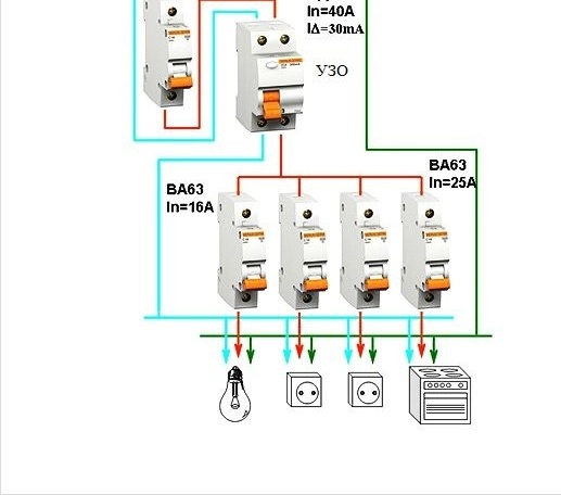
Option for an apartment with two-wire wiring
The specified scheme is also suitable for one group of consumers. For example, for kitchen electrical equipment and lighting. In this case, after an introductory circuit breaker, an UZO is installed, which protects the circuit section and electrical appliances located after it.
For a two-wire electrical network of a multi-room apartment, it is preferable to install an input RCD after the opening circuit breaker, and from the input RCD to branch the wiring to all the necessary groups of consumers, taking into account their capacity and installation location. In this case, an RCD with a lower differential current setting than the input RCD is set for each consumer group. Each group RCD is equipped with a circuit breaker without fail, this is necessary to protect against short circuit current and overload of the electrical network and the RCD itself.
An example of the electrical wiring diagram for a multi-room residential building, which is protected by residual current circuit breakers, is shown in the figure:
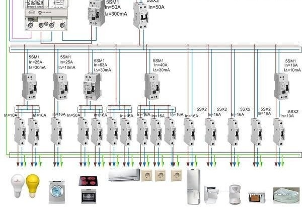
Option for multi-room
Another advantage of installing an introductory RCD is its fire protection purpose. Such a device controls the presence of the maximum possible values of the leakage current in all sections of the electrical circuit.
The cost of installing such a multi-level protection system is higher than that of a system with one RCD. The undoubted advantage of a multilevel system is the autonomy of each protected section of the circuit.
For an objective understanding of the process of properly connecting an RCD in a two-wire electrical circuit, a video is shown.
This video was found on the Youtube online resource, is used for educational purposes only and is not an advertisement.
Video: RCD installation diagram
RCD connection diagram in a three-wire (three-phase) electric circuit
Such a scheme is the most common. It uses a four-pole RCD, and the principle itself is preserved, as in a two-phase circuit using a two-pole RCD.
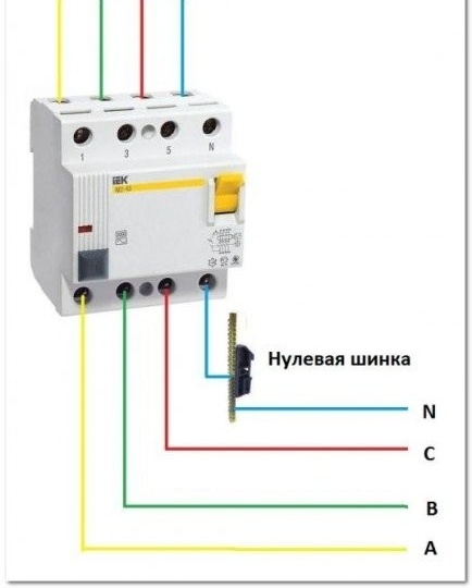
Four incoming wires, three of which are phase (A, B, C) and neutral (neutral), are connected to the input terminals of the RCD, according to the terminal marking (L1, L2, L3, N) applied to the device.
Wiring diagram
A similar scheme for the correct connection of wires to the device is located in the RCD passport or applied directly to the product body.
The location of the zero terminal may differ on RCDs of different manufacturers. It is important to observe the correct connection at the input and output of the device, the correct operation of the RCD depends on this. For the rest, the order of connecting the phases does not affect the operation of the RCD.
Three-phase network connection
It is important to remember that the rated operating currents of three-phase RCDs are relatively large. Such devices have more fire protection purposes, and separate RCDs with a lower rating for each section of the circuit are used to protect a person from electric shock.
For an objective understanding of the RCD connection diagram in a three-phase circuit, a diagram is given - an example.

Multi-level protection
It can be seen from the diagram that the branched electrical circuit after the introduction of the four-pole RCD is made similar to the two-wire circuit for connecting the RCD. As in the previous example, each section of the circuit is protected by an RCD device from leakage currents, and by a circuit breaker from short circuit currents and from overload in the network. In this case, single-pole circuit breakers are used. Only a phase wire is connected through them. The neutral wire approaches the RCD terminal, bypassing the circuit breaker. It is not necessary to connect the zero conductors to a common node after exiting the RCD, this will lead to false positives of the devices.
The input RCD in this case has a working current rating of 32 A, and RCDs in some sections have ratings of 10 - 12 A and differential current settings of 10 - 30 mA.
Errors during installation and connection of RCD
Typical errors when connecting RCD protective devices:
- As indicated above, the connection of the zero conductors to a common node after they exit the RCD. This causes the device to malfunction. To verify the correct assembly of the circuit, it is necessary to connect an electrical device to the outlet (whose circuit protects the RCD) and monitor the operation of the RCD. If it does not knock out, then the installation is completed correctly.
- The mistake is to connect the neutral and ground conductors. In this case, the RCD will not be able to respond to the difference in currents in the neutral conductor. Such a circuit design is fraught with frequent power outages and the danger of being energized with an inoperative ground loop.
- Connecting to the neutral wire of the RCD of the grounding conductors of sockets is also an error. Such actions are fraught with danger of exposure to stress. And also this circuit can cause a short circuit.
For greater clarity, a video is presented on the topic of typical errors with self-installation of RCDs.
This video was found on the Youtube online resource, is used for educational purposes only and is not an advertisement.
Video: errors when connecting a protective device
Undoubtedly, human safety is a priority in the operation of any equipment, especially electrical. Implementing safe power supply circuitry is often an overwhelming task for an unskilled person. If the decision to install the protective elements of the power grid is made, but doubts remain, it is best to contact professionals. Indeed, the correct and safe operation of any electrical equipment directly depends on the quality of installation.