DIY hidden wiring detector
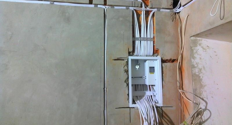
When carrying out repairs in an apartment, it is often necessary to search for electric wires walled under the finish. It is very convenient to do this with the help of a hidden wiring finder, which can be purchased at a specialized store or built on your own.
Content
What are the hidden electrical wiring warning devices for?
Hidden wiring detectors help to detect wires embedded in the walls in case the apartment is being prepared for repair, and they are also needed to find a break in the wiring. In addition, such a device will help determine which particular lamp burned out on the New Year's garland.

You can find electrical wires walled under the trim using a hidden wiring detector
Even if you are sure exactly where the wire goes in the wall, be sure to turn off the voltage before starting work with electricity.
Types of Indicators
Covert wiring alarms come in many types. They differ in principle of operation, method of notification of wire detection, physical characteristics of wiring and other parameters. Each type of indicator has its pros and cons.
Table: pros and cons of various types of covert wiring detectors
| Flush Detector Type | Operating principle | pros | Minuses |
| Electrostatic | Defines an electric field that generates voltage when connected to electricity. | Simple scheme, action at a great distance. | Search exclusively in a dry environment, the desired conductors must be energized. |
| Electromagnetic | Captures an electromagnetic field that creates an electric current in the wires. | Simple circuit, high detection accuracy. | The required conductors must be energized and connected to a load with a power of 1 kW or more. |
| Inductive (conventional metal detector or metal detector) | When wires are detected, it determines the changes in the electromagnetic field that it creates. | No voltage required. | Complex construction, responds to any metal (including nails hammered into the wall). |
| Combined (factory manufacturing) | Uses various principles of action. | Increased accuracy, sensitivity and performance. | High price. |
It is easiest to independently make an electrostatic indicator of hidden wiring, the operation of which is based on the principle of voltage multiplication.
Examples and comparison of popular models
On sale you can find various factory-made detectors.
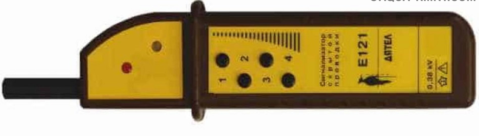
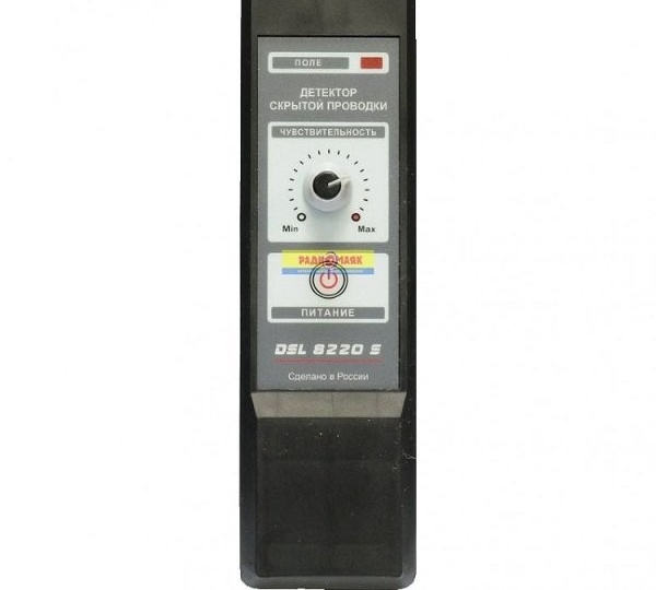
- Finder of hidden electrical wiring "Woodpecker". It is a multifunctional device for working with electrical networks. Hidden wiring tester is included in its design. In the complex instrument "Woodpecker" several indispensable gadgets are connected at once. The device has 4 levels of susceptibility. The highest allows you to find electrical wiring and metal objects at a depth of up to 700 mm. The conductor location error is 10 mm. Perhaps because he is domestic.
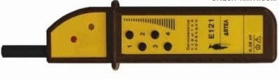
The Woodpecker tool is a multifunctional device, one of the purposes of which is to search for wires walled into the wall
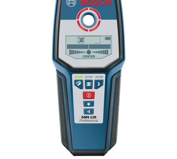
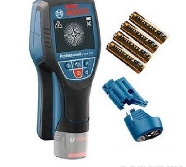
- The Bosch GMS 120 Professional metal detector and wiring indicator detects live wires at a depth of 50 mm, ferrous metals at a depth of 20 mm, non-ferrous metals at a depth of 80 mm.
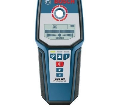
Bosch GMS 120 Professional metal detector and wiring indicator finds live wires at a depth of 50 mm
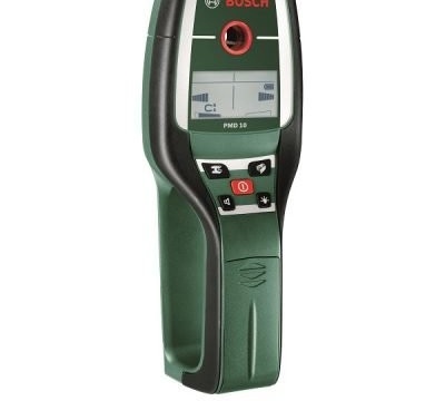
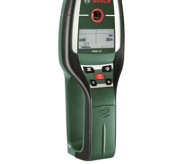
- The Bosch PMD 7 wiring indicator detects wires and metals at a depth of 70 mm with maximum warranty. Drilling is performed according to the LED. The device is controlled with just one button.

The device is controlled with just one button and finds wires at a depth of up to 70 mm
- Metal and wiring indicator LUX-TOOLS. The maximum detection depth of wiring and any metals is 30 mm.
The LUX-TOOLS device is inexpensive and can determine the location of wires in a city apartment
- The CEM LA-1010 481172 laser hidden sound wiring detector with laser indicator detects materials at a depth of 20 mm. Its distinctive feature is that in addition to wires and metals, it also reacts to wood, that is, it helps to find wooden structures.
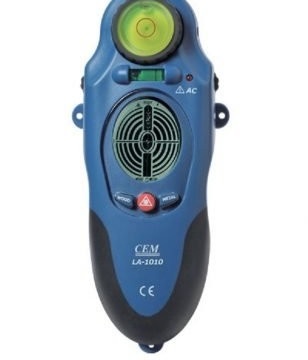
This device will help to find not only wires, but also wooden structures
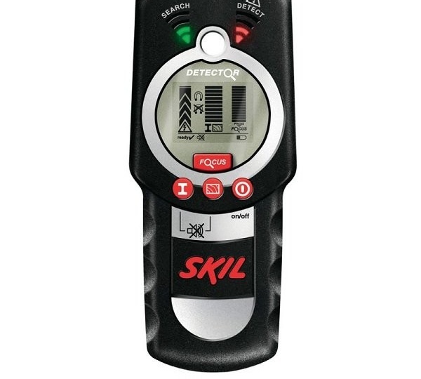
- The Skil 0550 AA Multifunction Wiring Detector works at a depth of up to 80 mm. He is looking for live wires, ferrous and non-ferrous metals, wooden structures. Convenient reading of information provides a large LCD display.
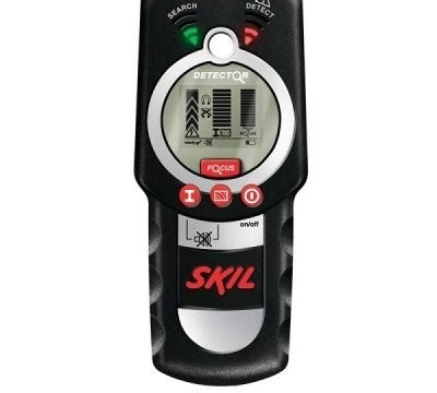
The Skil 0550 AA can detect deep-seated wires as well as metal and wood objects.
- The Skil 0550 AB multi-detector is less capable. He only searches for live wires, ferrous and non-ferrous metals at a depth of not more than 50 mm.

This detector will help you find live wires and metal structures (for example, reinforcement in concrete when drilling)


Selection recommendations
Which hidden wiring detector is better: imported, domestic or do-it-yourself? In principle, there are no special complaints about the work of both foreign and Russian testers. Therefore, when choosing a device, the installer must determine for himself its necessary characteristics:
- appearance;
- functionality;
- basic electrical parameters;
- ease of use;
- other details.
However, the following should be noted here. Since domestic detectors are manufactured in accordance with the electrical standards of Russia, their functions when searching for hidden wiring will also correspond to domestic standards for wiring.
Domestic detectors are manufactured in accordance with the electrical standards of Russia
Foreign devices comply with the regulations of the countries in which they are manufactured. This means that they will not necessarily be adapted to our conditions. In addition, they cost an order of magnitude more expensive than domestic appliances.
Foreign devices comply with the regulations of the countries in which they are manufactured and are more expensive
When making a DIY wiring tester, it is necessary to minimize the possible disadvantages of the created device. It is better to carry out such work under the guidance of an experienced specialist.
When making a DIY wiring tester, it is necessary to minimize the risk of defects in the created device
DIY indicator charts
By the method of warning about the finding of hidden wiring, the indicators are divided into acoustic, visual, combined, etc. Let us give examples of various options for design solutions for self-assembly of a signaling device for hidden wiring.
Before using the hidden wiring finder, created independently, it is necessary to check its operability and calibrate.
Diagram 1: acoustic finder
We present to your attention a diagram of the most basic finder with acoustic indication. The microchip protects the resistor R1 from the induced voltage. However, it does not directly affect the operation of the device, so it can be excluded.
The antenna in this device is a copper conductor. Its length can be 50-150 mm. Detection of an electric wire will be accompanied by a special crack made by a piezoelectric element. The inclusion of a piezoelectric element in a bridge circuit allows you to increase the volume of the device.
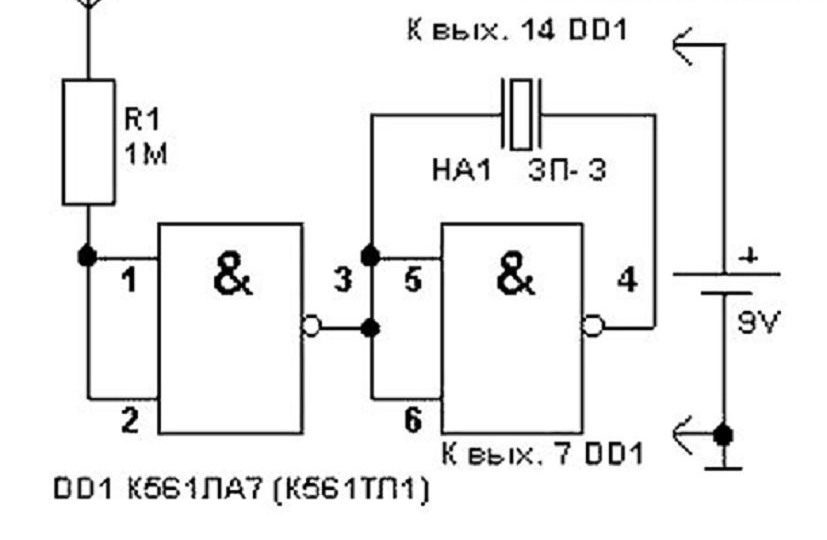
If wires are detected in the wall, the device will make a crack that generates a special piezoelectric element
Diagram 2: detector with acoustic and visual indication
The layout of the acoustic and visual indication device is also quite simple. It is not at all difficult to assemble such a seeker yourself. The device is assembled on one microchip. The uniqueness of the presented circuit lies in the fact that the resistor R1 has a resistance of at least 50 megohms and fully protects the circuit from induced voltage. The limiting resistance of the LED diode is not necessary, since the microchip itself copes with this function perfectly.
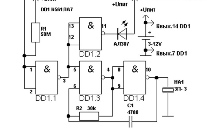
The device is assembled on one microchip and works stably due to the presence of a limiting resistor
Circuit 3: Field-Effect Transistor Finder
It is quite easy to build an indicator of a hidden electrical wiring according to a scheme with a field (unipolar) transistor independently. Even someone who does not have much experience in handling electrical equipment will cope with this. To assemble this tester is no more difficult than to make an elementary electric circuit. We were taught this in high school.
Before assembling the device, you must take care of the availability of the following tools and parts:
- soldering iron, rosin, solder;
- stationery knife, tweezers, nippers, field transistor KP303 or KP103;
- a speaker with a resistance of 1600–2200 Ohm (can be taken from a landline telephone);
- 1.5–9 V batteries;
- circuit breaker;
- a small plastic container in which the installation of parts will be carried out;
- wires.
Since the field-effect transistor is vulnerable to electrostatic breakdown, metal tools should be grounded, and in no case should you touch the terminals of the semiconductor element with your fingers.
The functioning of this device is based on a system for trapping an electric field. The diagram shows that, due to a change in the thickness of the n-p junction, the source-drain transition decreases or the conductivity of the indicator increases. Since the change in the electric field occurs with the network frequency, the speaker responds to the detection of wires with a characteristic drone with a power of 50 Hz, which amplifies when approaching the target.
When assembling the device, refer to the designation of the terminals of the transistor so as not to confuse them. In the above diagram, the control terminal that responds to the amplification or decrease of the electric field is the gate. Therefore, the field effect transistor must be enclosed in a steel casing connected to the gate. It will play the role of an antenna that receives pulses of electrical wiring.
In order to visualize the moment when the electrical wiring is located, it is possible to connect an arrow pointer with a ballast resistor from an unnecessary tape recorder or a milliammeter with a resistance of 1-10 kΩ in parallel to the source-drain circuit. Mounted pointer on single-core wires of sufficient elasticity. When approaching the wires hidden in the wall, it will respond to the amplification of the electric field.
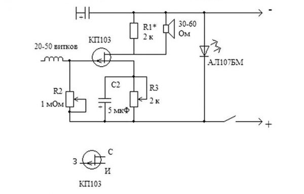
The field-effect transistor finder has a simple circuit and can be supplemented with a dial indicator to visualize the operation
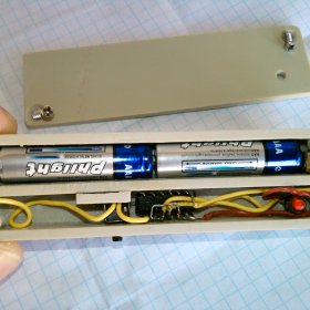
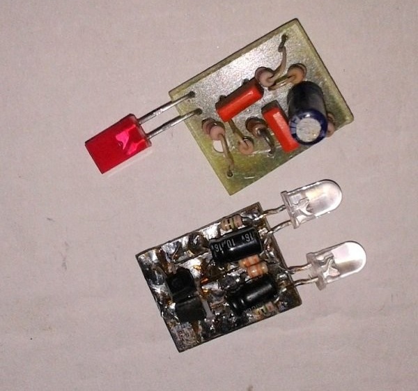
Figure 4: wire break alarm
The wire break detector is also easy to assemble with your own. It is a compact device that can even be placed in the case from a conventional stationery marker, stretching the antenna through the vent. The length of the antenna should correspond to the depth of the electrical wires in the wall. Usually this value is up to 100 mm. If the wiring is not laid so deep, the length of the pole of a polevichka (field-effect transistor) is enough.
The unipolar transistor VT1 acts as a directly tester, with a sufficiently powerful susceptibility. When the transistor gate is in the maximum proximity to the electrical wires, the drain-source resistance will decrease. As a result, the remaining transistors will open and the indicator light will light.
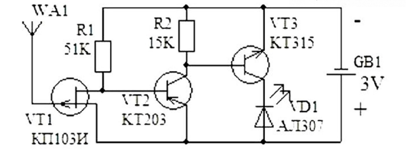
In this scheme, the elements VT1 and D1 can be replaced with any analogues that are at hand
Kolevich KP103 and LED-lamp AL307 can be replaced with any analogues. Bipolar transistors can be installed those that are available, but they must have similar conductivity and low power. The transmission coefficient, in contrast, should be large enough. Instead of the KT203 transistor, it is permissible to use the KT361 transistor. During installation, KP103 pole must stand horizontally, and its shutter must be bent so that it is above the transistor housing.
Video: how to assemble a do-it-yourself hidden wiring detector
Which version of the hidden wiring tester you stop at depends on your needs and skills in working with electricity. But a DIY tool will become your first assistant and will undoubtedly please you for a long time.