How to connect a dimmer yourself
Dimmer is the newfangled name of the device, often referred to as a dimmer in our country and designed for continuously controlling the power of electrical appliances, primarily fixtures (in English, “dim” means “dim”). The thing in the household is very useful, but buying it is not necessary. In the sense that anyone, at least once holding a soldering iron, can make such a device with their own hands. Next, we describe how this is done.
Content
Types of Dimmers
The simplest kind of dimmers can be considered any variable resistor, for example, a rheostat known to everyone since school. If you turn it on sequentially with an incandescent lamp, then when you change the position of the slider, its brightness will change. However, it is extremely unprofitable to use such a dimmer, since it does not reduce the power consumption, but only “pulls” part of it onto itself, turning it into heat.
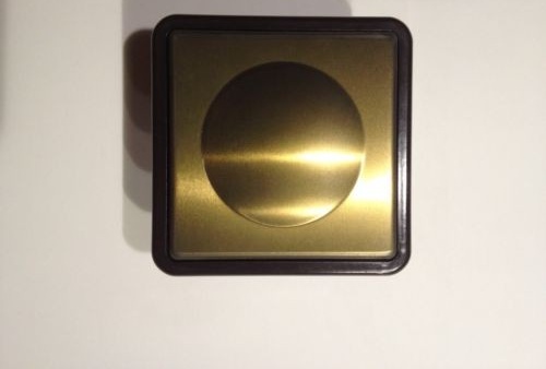
General view of the dimmer
A practical option for a dimmer is an autotransformer. The secondary winding of this device has several pairs of terminals on which a different output voltage is generated. When connecting a load to a particular pair, it will work with different power.
Autotransformer dimmers have several advantages:
- consume from the supply network only the power that is currently needed;
- regardless of the ratio of input and output voltages, they produce a sinusoidal current with virtually no distortion;
- Do not interfere.
But such devices have a relatively large size and weight, and mechanical switches have to be used for adjustment, so they are used today only in rare cases.
To date, electronic dimmers assembled on semiconductor elements have become popular. These are compact, weightless devices.
It is also possible to regulate the intensity of lighting in the room using the three-key switch. Details of its connection:https://aquatech.tomathouse.com/en/ehlektrosnabzhenie/kak-podklyuchit-trehklavishnyiy-vyiklyuchatel.html
The principle of operation of the electronic dimmer
Power regulation does not consist in voltage conversion, as is the case with a transformer: a dimmer transmits current only at a certain value of it (voltage).Recall that the voltage in the AC network constantly fluctuates in a sinusoid from -230 V to + 230V.
Factory-made electronic dimmer
That is, the electronic dimmer is a high-frequency switch that manages to turn on and off during each half-cycle of alternating current. Thus, the load is not connected to the network all the time, but only during a certain fraction of the half-cycle, due to which the average voltage and electric current power decrease.
Obviously, the current at the output of the electronic dimmer has a far from sinusoidal characteristic: it is rather a kind of its alternatingly pulsating variety. If you build a graph, part of each wave of the sinusoid will be cut off, as it were.
It is important to know that such food is not suitable for all devices. In those of them that require a current with a low harmonic coefficient, the winding may overheat, as a result of which the device will fail.
Of household consumers, this category primarily includes:
- electric motors;
- devices with a switching power supply;
- devices with transformer power: televisions, radios, fluorescent lamps with electronic ballast;
- induction transformers of halogen lamps.
But all that has been said applies only to the simplest electronic dimmers with a classical circuit. More sophisticated dimmers, which are currently not only developed, but are also mass-produced, are omnivorous - they can be connected to any load. The main thing is to choose the right model.
Electronic dimmers have one more drawback: in the simplest version (such models are the cheapest) they are a source of noticeable electromagnetic interference both in the radio frequency range and in the wires connected to them. In the room where the dimmer is installed, it may be difficult to listen to the radio receiver, there may be irregularities in the operation of the measuring equipment, as well as sound recordings in the form of a background.
There is a solution - you need to improve the circuit by adding a filter to it. In this quality chokes are used, they can be supplemented with capacitors (inductive-capacitive filter). Filter dimmers are slightly more expensive.
An incandescent lamp, to which a voltage reduced by an electronic dimmer is applied, emits a whistling sound, barely audible, but clearly visible in complete silence. The more powerful the lamp, the more intense the whistle will be. The fact is that the peculiar current received at the output of the dimmer causes mechanical vibrations in the filament, which lead to the appearance of such a sound.
This phenomenon is called magnetostriction. It takes place when connected directly, that is, without a dimmer, but in this case it manifests itself to a much lesser extent, and does not produce sounds heard by a person.
How to make a device with your own hands
The usual dimmer is simple and cheap to manufacture, since it requires a small number of completely affordable radio components. Here are the main ones:
- Thyristor: This is a semiconductor element in which there are three or more pn junctions. Two control electrodes are connected to the external semiconductor layers - the anode and cathode. By applying a control signal to these electrodes, the thyristor can be switched to one of two states - “open” (conductivity becomes high) or “closed” (conductivity becomes low), that is, it works like an electronic switch.
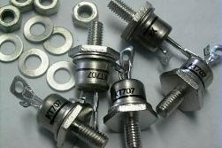
Thyristors
- Triac: the full name of this semiconductor device is a symmetric triode thyristor, that is, it is a variation of the group of elements just described. Each of the control electrodes of the triac is simultaneously an anode and a cathode. Being in the open state, it passes current in both directions (the thyristor is in only one direction). To keep it open it does not require a constant supply of a control signal.Like a thyristor, a triac plays the role of a controlled electronic switch (such an element is often called a key). Based on these devices, the power part of the dimmer circuit is assembled.
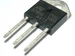
Triac
- Dinistor: another element of semiconductor materials, the full name is a bi-directional diode. It is similar in structure to a thyristor, but it does not have control electrodes. By the principle of operation, it is similar to a safety valve: as soon as the voltage at the contacts reaches a threshold value, it opens. In dimmers, such elements are used in control circuits (participate in the formation of a control signal).
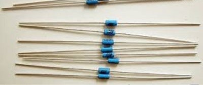
Dinistors
- Other details - resistors, diodes, capacitors, whose functions are known to all.

A few words are worth saying about the dimmer assembly. The simplest is the so-called mounted installation, when all the elements are connected into a single circuit by means of wires.
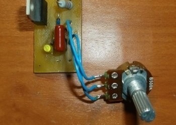
It looks like a dimmer assembled in a hinged way
Before soldering, the stripped wires of a piece of wire cut to the desired length, as well as the “legs” of the radio components, must be tinned using a soldering iron (solder and a special flux or rosin are used).
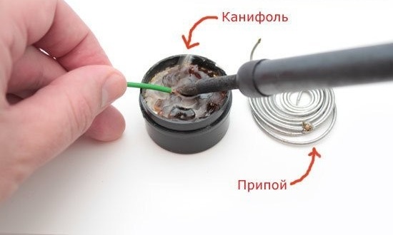
Materials for connecting wires by soldering
After soldering, all connections should be wrapped with electrical tape. If this is not done, an accidental contact or moisture can cause a short circuit.
A more complex option is to assemble a dimmer on a makeshift printed circuit board.
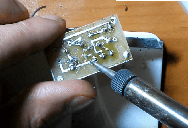
PCB Dimmer Assembly
Its manufacture requires some skill, but the device will turn out to be miniature and more reliable. The tracks on the board, as well as the wire strands for surface mounting, must be tinned. The soldering process is also no different.
Now consider a few electronic dimmer circuits.
On the triac
This device is designed to connect to a network with a voltage of 220 V. As you can see, in addition to the triac and dinistor, there is an RC chain. It has a voltage divider consisting of a variable resistor R1 and a constant R2.

Triac dimmer circuit
The scheme works as follows:
- The user sets the resistance R1, on which the voltage in the circuit R2 - C1 depends. From this voltage, in turn, depends on the charging time of the capacitor C1.
- When the voltage on it reaches a certain value, it causes the DB3 dinistor to open, which is included in the same circuit between R2 and C1.
- At the same time, through DB3, a pulse is applied to the triac VS1, it opens and passes current to the load. The faster C1 is charged, the sooner VS1 opens and, accordingly, the longer will be that part of the half-cycle during which current is passed to the load. Consequently, the electric power will be greater.
The process of controlling the intensity of lighting with such a dimmer is displayed on the graph:
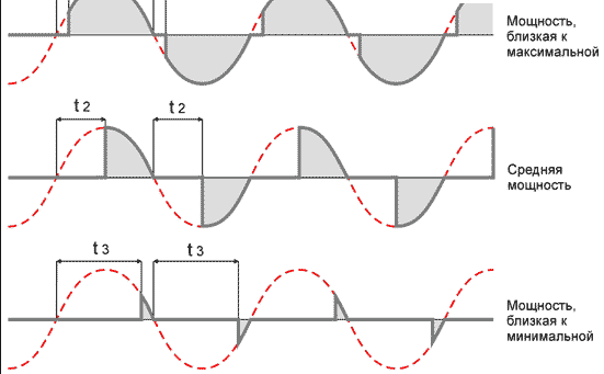
Lighting Interval Schedule
The time during which the charge in C1 reaches the opening threshold DB3 is denoted by t *.
On thyristors
Thyristors are good in that they can be removed from old electrical appliances, such as televisions. Thus, the dimmer will be almost free. Here is his diagram:
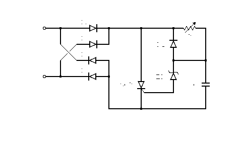
Thyristor dimmer circuit
Thyristors, unlike triacs, pass current in only one direction, so for this dimmer they will need two - one for each half wave of alternating current. Accordingly, two dinistors will be needed, through which, as in the first circuit, a control pulse is formed.
According to the principle of operation, the circuit is very similar to the previous one:
- The positive half-wave through the circuit R5 - R4 - R3 charges the capacitor C1.
- As soon as the voltage on C1 is sufficient to open the V3 dynistor, it (the dynistor) will pass a control pulse to the thyristor electrode V
- V1 will open and pass current to the load.
- With a negative half-wave, the thyristor V2 will operate in a similar way, while V1 will be closed. In this case, the capacitor is charged through the circuit R1 - R2 - R
Condenser dimmer
Unlike the first two, this dimmer option allows you to reduce power only by a certain fixed amount, that is, an intermediate brightness level of the lamp appears. But it is very compact.
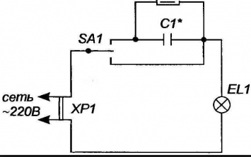
Condenser dimmer
The principle of operation is extremely simple. As you know, an alternating current can flow through the circuit into which the capacitor is connected, but its power will depend on the capacitance of the capacitor. The faster it charges (low capacity), the smaller the fraction of half-wave will have time to go through the circuit. And vice versa - with a large capacity, even the entire half-wave can do useful work.
Therefore, you need to select a capacitor with the required capacity and connect it to the circuit so that it is possible to direct current either through it (reduced power) or bypass (100 percent power).
You can include another capacitor in the circuit with the ability to switch between it and the first capacitor (you will need a 4-position switch). Then an additional power adjustment step will appear.
Capacitors can be used paper, non-polar, available in abundance in old electrical appliances. Their capacity is selected according to the following table:
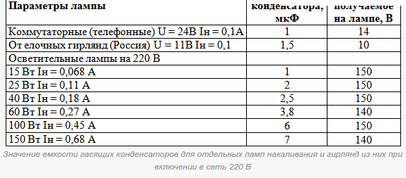
Capacitance-voltage parameter table
On the chip
Now we will consider a dimmer for direct current with a voltage of 12 V. Such a regulator is most conveniently assembled on a KREN microcircuit - an integral stabilizer.
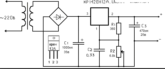
Chip Dimmer
Due to the use of the microcircuit, the design of the device is extremely simplified, respectively, the amount of assembly work becomes minimal. In addition, such dimmers have a protection function.
To adjust the power, as in the first two circuits, a variable resistor is used (in the diagram - R2). The value of the reference voltage at the KROEN control electrode depends on its resistance, on which, in turn, the output voltage depends. The adjustment range is very wide - from 12 V (100%) to a few tenths.
It should be noted that the CRANK chip is quite hot, which is why it has to be equipped with a relatively large radiator. To a much lesser extent, this drawback manifests itself in dimmers assembled on the basis of the integral timer 555 and the KT819G transistor controlled by it (plays the role of an electronic switch like a thyristor and triac).
The control signal is short PWM pulses that switch the transistor either to the fully open or to the fully closed position, so that the voltage drop across it is the smallest possible. Accordingly, the circuit turns out to be more economical than on the basis of KREN, and due to the use of a smaller radiator, it is also more compact.
Finished Dimmer Selection
If you decide to purchase a factory-made dimmer, pay attention to the following:
Specifications
There are only two of them:
- mains voltage;
- permissible load power.
For example, for a chandelier with three ordinary incandescent lamps of 100 W each, a dimmer with characteristics of 230 V / (25 - 400 W) is suitable. Permissible power is always indicated in the form of a certain range, the upper value of which should be taken with some margin.
Note! For some Chinese dimmers, for example, from the Powerman company, an interesting feature is noticed: one power value is indicated on the label, and another on the instrument case. Moreover, these values can vary quite a lot, for example, “600 W” is written on the label, and “25 - 400 W” on the case.
Therefore, when buying a cheap imported dimmer, do not limit yourself to studying the information on the box - be sure to consider the device itself.
Load type
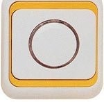
The simplest dimmers are designed to control the power of incandescent and halogen lamps.
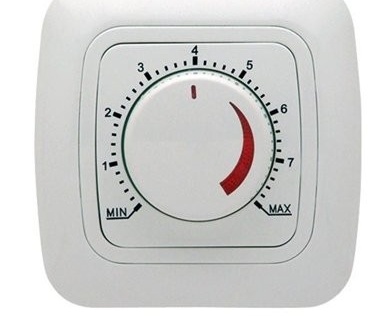
Rotary dimmer for incandescent lamps
More advanced models can also work with low-power electric motors - usually fans are connected through them.An example is the Kopp Dimmat dimmer (Germany).
One of the representatives of the Kopp Dimmat dimmer range
Dimmers are also available through which fluorescent lamps can be connected. If any of the mentioned loads is powered through a simple dimmer, then it can fail.
It is important to know that not every such lamp can be connected to a dimmer designed to connect, for example, fluorescent lamps. It should be marked "dimmable" or, equivalently, "dimable".
Control method
On this basis, dimmers are divided into several varieties:
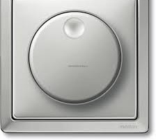
Mechanically controlled
These are the simplest and cheapest devices. They have a rotary knob, which is why they are usually called rotary knobs. As an example, we can cite the domestic model “Bella S16–65”. Rotary dimmers have minimal functionality. To turn off the light, you need to turn the knob to the extreme position until it clicks, to turn it on - turn it to the other side by a certain angle, on which the brightness of the light will depend. The inconvenience of this control method is the lack of a function for storing settings - the brightness of lighting has to be set up anew each time it is turned on.
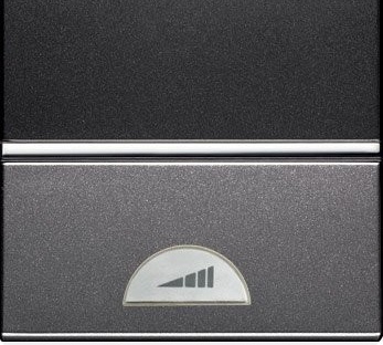
Electronically controlled
These dimmers are divided into keyboard and touch. There are also pseudo-sensor ones, for example, the Simon 75305–39 model, the keys of which are pressed with such low effort that they hardly differ from the touch panel.
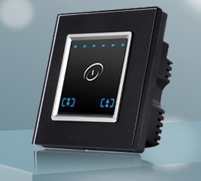
Touch dimmer for LED bulbs
Typically, the keys and touch panels have a double effect: with a short press / touch, the light turns on or off, with a long hold - the brightness of the light changes. When you turn on the lamp, the brightness will immediately turn out to be the same as it was set before turning it off, that is, it is no longer necessary to adjust the light each time again.
Note! Along with the usual dimmers are produced, which, when the lamp is turned on, supply voltage to it with a smooth build-up. It is believed that such dimmers prolong the life of the lamps.
An example of a dimmer with touch control is the SM180 model of the Eunea Merlin Gerin brand (Spain). In addition to conventional luminaires (incandescent and halogen lamps at 230 V), this regulator can be used to connect low-voltage halogen lamps with a conventional (ferromagnetic) transformer.
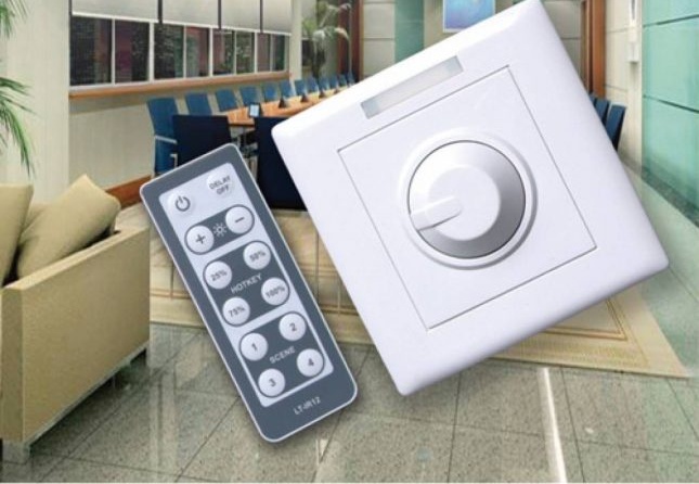
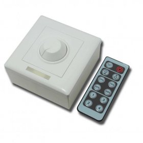
With remote control
Control signals can be transmitted both through infrared (IR) radiation, and using radio frequency. For example, the IR-receiver is equipped with the Smart Dimmer Pro 21 model of the French company Legrand.
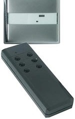
Model Smart Dimmer Pro 21
You can connect to it:
- low-voltage halogen lamps not only with conventional, but also with electronic transformers;
- luminescent lamps with electronic ballasts.
The ability to work with such loads is due to the presence of a phase cut-off switch on the leading / trailing edge.
Total power - up to 500 watts.
The remote control can be used not only branded, but also any other with support for the RC5 code.
With sound control
These devices can respond to pops or even voice commands.
To independently connect a cotton switch, this material will help:https://aquatech.tomathouse.com/en/ehlektrosnabzhenie/vyiklyuchatel-sveta-po-hlopku.html
Options
Many of the modern dimmers are equipped with an additional terminal, to which you can connect conventional push-button switches. With their help, you can control the lighting in the room from several places.
There are models equipped with a timer, for example, the already mentioned Simon 75305–39 pseudo-sensor dimmer.
Pseudo-sensor dimmer Simon 75305–39
After the time set by the user, the device will automatically turn off the light.
The widest range of possibilities is provided by programmable dimmers equipped with a microcontroller. They can have such functions:
- imitation of the presence of tenants (automatic switching on and off the light in order to mislead apartment thieves watching the windows);
- brightness control in various modes, for example, blinking at a certain frequency (Strobe);
- management of several groups of fixtures (zones) and memorization of various lighting scenes for them.
A good example of a programmable dimmer is the Lutron Grafik EyE system (USA).

Lutron Grafik EyE Dimmer
Here is how its multi-zone is manifested: the user can connect several groups (up to 6) to the system, for example, a chandelier, wall lamps and decorative lights, and then set a brightness value for them for different occasions.
For example, when a family gathers at a festive table, the brightness of the chandelier is set to 70%, and the brightness of wall and decorative light sources is set to 20%. Another scene is set up for watching TV: the brightness of the chandelier decreases to 20%, the brightness of other lamps increases to 30%.
The settings for all lighting scenes (their maximum number is 16) are stored in the system memory, so that you can easily switch between them - both quickly and smoothly (the process of switching from one scene to another can be extended for an hour).
The Grafik EYE system can be controlled using the remote control, it can work only with incandescent lamps.
The maximum total load power is 2300 watts, while the maximum for each zone is negotiated is no more than 800 watts. The capabilities of the system can be expanded by connecting a power amplifier to it. Then the limit for each zone will increase to 1800 watts.
Programmable dimmers are also available in the CIS countries. For example, the Sapphire 2503 model of the Belarusian company Nootekhnika supports the presence simulation mode and has a timer that turns off the light 12 hours after the last user action. The dimmer has a touch panel and can be controlled by a remote control. The current to the load when turned on is supplied in increasing increment (which extends the lamp life).
Useful Tips
Carefully read the product passport. Some dimmers heat up significantly, so manufacturers prescribe their use with restrictions. So, for example, the Dimmat dimmer of the German company Kopp is not recommended to be switched on with a load of more than 300 W if the room temperature exceeds + 25 ° C: but the maximum allowable power declared in its characteristics is 400 watts.
An article on the self-manufacture of a passage switch is located here:https://aquatech.tomathouse.com/en/ehlektrosnabzhenie/kak-sdelat-prohodnoy-vyiklyuchatel.html
Such requirements should be taken with special attention if the wall on which the device is supposed to be mounted is made of materials with low thermal conductivity, for example, wood or drywall.
You should know that the efficiency of the bulb, "screwed" with a dimmer, is greatly reduced. Therefore, in the event that you have to use the lamp most of the time in the reduced brightness mode, it is more advisable to replace it with a less powerful one and use the latter without a dimmer.
The most “tenacious” are domestic rotary dimmers. So, for example, the already mentioned “Bella S16–65” model is able to work with voltage surges from 60 to 285 V.
All modern dimmers have a fuse, so it makes sense to purchase at least one spare in advance.
Note! When with dimmer switch the power of a low-inertia light source, for example, an LED strip or a discharge lamp, decreases; a stroboscopic effect takes place. In such lighting, moving or rotating mechanisms and tools may seem motionless, which is very traumatic. Therefore, in workshops and production premises, dimmers should be used with caution.
How to connect a dimmer
In the general case, the dimmer is connected like an ordinary switch, but there is a condition: the regulator should only be included in the phase break (the switches can be installed both in phase and in “zero”).
In practice, dimmers are often installed in pairs or with switches.
Dimmer connection diagram
Dimmers are connected like switches. Both of these elements are mounted in series with the load. The dimmer can be safely put in place of a conventional switch. To do this, turn off the mains power, disconnect the wires from the terminals of the old switch, and install a dimmer in its place. This operation is also simplified by the fact that the installation dimensions of the dimmers correspond to the dimensions of simple switches.
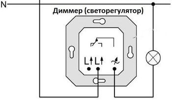
Dimmer connection diagram
When connecting a dimmer to the mains, remember: it must be included in the phase (L), and not the neutral (N) wire.
Circuit breaker
Such schemes are extremely convenient: they allow you to control the intensity of lighting from anywhere in the apartment. In the bedroom. For example, it is advisable to install a dimmer next to the bed - in this case, the user does not have to leave a warm bed to reduce or increase the light intensity.
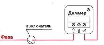
Wiring diagram for dimmer with switch
Such a scheme is appropriate to use in smart home systems. Effective light control allows you to highlight individual areas of the room or interior details. A simple switch is installed near the interior door. They use it when entering and leaving the room - when you need to turn on or off the light.
Installation scheme with two dimmers
If necessary, you can adjust the light intensity from two points. in this case, two dimmers are installed, and their first and second terminals are interconnected. A phase wire is connected to the third terminal of any of the dimmers.
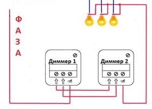
Connection scheme with two dimmers
The wire to the load comes from the third terminal of the remaining dimmer. As a result of such manipulations, three wires should exit the junction box of each of the dimmers.
Switching on a dimmer with two pass-through switches
The principle of operation of this circuit is as follows: one switch is installed at the entrance to the room, the second - at the other end of the stairs or corridor. In this case, the dimmer is mounted between the switch and the load in the phase wire.
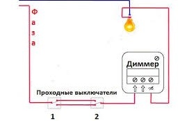
Wiring diagram for dimmer with two loop-through switches
You cannot install a dimmer between the breakers.
Please note: if the dimmer in this circuit is turned off, none of the pass-through switches will work.
Connecting a dimmer to LED strips and lamps
If you connect a dimmer to the LED strip, you will be able to change the brightness of its glow. Choose a dimmer for the total power of the LED strip.
When implementing this scheme with monochrome tapes, a power supply unit is connected with a dimmer. The conclusions of the dimmer are connected to the load itself, while observing the polarity of the current.
In the case of the use of LED strips having RGB channels, the dimmer is also connected to the power supply, and its conclusions to the signal controller.
The power of the dimmer in any of the above cases should be 20-30% higher than the estimated power consumption of the tapes.
Please note: special dimmers are available for working with LED lamps and ribbons.
Video: how to replace a switch with a dimmer
Dimmers are very popular, and this encourages manufacturers to actively develop this industry of instrumentation. To date, we have learned to make regulators for any type of load, including one with transformer power supplies. But if we talk about ordinary incandescent or halogen lamps at 220 V, then the dimmer for them is an extremely simple device and, as the reader could see, it is quite easy to do it yourself.